Super-Precision Contact Ball Bearings Preload, Clearance And Stiffness
A single super-precision angular contact ball bearing cannot be preloaded until a second bearing provides location in the opposite direction.
Bearings manufactured pre-set for preload
Universally matchable bearings and matched bearing sets are manufactured pre-set in different preload classes to meet varying requirements regarding rotational speed, rigidity, and operating temperature.
The amount of preload depends on the bearing series, the contact angle, the internal geometry, and the size of the bearing and applies to bearing sets in back-to-back or face-to- face arrangements. Preload values are not standardized and are listed in the product table.
Bearings in the S70 .. W series are manufactured as single universally matchable bearings or as matched sets of two bearings. In either case, arranged back-to-back or face-to-face, standard preload prior to mounting is zero.
Matched bearing sets with a special preload can be supplied on request. These bearing sets are identified by the designation suffix G followed by a number. The number is the mean preload value of the set expressed in daN. Special preload is not applicable for sets of universally matchable bearings consisting of three or more bearings. Matched bearing sets consisting of three or more bearings have a heavier preload than sets with two bearings. The preload for these bearing sets is obtained by multiplying the values for a single bearing by a factor listed in table 1
Bearings in the 719 .. D, 70 .. D and 72 .. D series are manufactured to four different preload classes:
- Class A, extra light preload
- Class B, light preload
- Class C, moderate preload
- Class D, heavy preload
Bearings in the 718 .. D, 719 .. E and 70 .. E series are manufactured to three different preload classes:
- Class A, light preload
- Class B, moderate preload
- Class C, heavy preload
These preload classes are valid for:
- Single, universally matchable bearings
- Sets of universally matchable bearings
- Matched bearing sets
In applications where high speeds take precedence over the degree of rigidity, the following additional preload classes are available:
- class L, reduced light preload for asymmetrical bearing sets
- class M, reduced moderate preload for asymmetrical bearing sets
- class F, reduced heavy preload for asymmetrical bearing sets
As indicated, these preload classes are only available for matched bearing sets that are asymmetrical, e.g. TBT, TFT, QBT, and QFT. Bearing sets in the L, M or F preload class consisting of three or four bearings, have the same preload as sets with two bearings in the A, B or C preload class. Therefore, the preload for matched bearing sets that are asymmetrical, e.g. TBT, TFT, QBT, and QFT, can be obtained directly from the product table.
An example of the preload possibilities for an arrangement with a matched set of 7014 CE bearings is presented in table 2.
Bearings in the 719 .. B and 70 .. B series are manufactured to three different preload classes:
- Class A, light preload
- Class B, moderate preload
- Class C, heavy preload
Preload in mounted bearing sets
After mounting, sets of universally matchable bearings and matched bearing sets can have a heavier preload than the pre-set preload, predetermined during manufacture. The increase in preload depends mainly on the actual tolerances for the shaft and housing seats and whether these result in an interference fit with the bearing rings.
An increase in preload can also be caused by deviations from the geometrical form of associated components, such as cylindricity, perpendicularity or concentricity of the bearing seats.
During operation, an additional increase in preload can also be caused by:
- The centrifugal force caused by the rotational speed of the shaft, for constant position arrangements
- A temperature difference between the inner ring, outer ring, and balls
- Different coefficient of thermal expansion for the shaft and housing materials compared to bearing steel
If the bearings are mounted with zero interference on a steel shaft and in a thick-walled steel or cast iron housing, preload can be determined with sufficient accuracy from
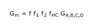
where
Gm Preload in the mounted bearing set [N]
GA,B,C,D Pre-set preload in the bearing set, prior to mounting [N] product table
f PBearing factor dependent on the bearing series and size product table
f1 Correction factor dependent on the contact angle product table
f2 Correction factor dependent on the preload class product table
fHC Correction factor for hybrid bearings product table
Considerably tighter fits may be necessary, for example, for very high speed spindles, where centrifugal forces can loosen the inner ring fit on its shaft seat. These bearing arrangements must be carefully evaluated. In these cases, contact the application engineering service.
For preload in a mounted bearing set (Gm) of S70 .. W series bearings, contact the applications engineering service.
Calculation example
What is the preload in a matched bearing set 71924 CD/P4ADBC after mounting?
The pre-set preload for the set of two bearings in the 719 CD series, prior to mounting, preload class C, size 24 is GC = 1 160 N roduct table.
With the bearing factor f = 1,26 and correction factors f1= 1 and f2= 1,09 product table, the preload of the mounted bearing set is
= 1,26 x 1 x 1,09 x 1 160 ≈ 1 590 N
Preload with a constant force
In precision, high-speed applications, a constant, uniform preload is important. To maintain the proper preload, calibrated linear springs are typically used between the bearing outer ring and housing shoulder. With springs, the kinematic behaviour of the bearing does not influence preload under normal operating conditions. However, a spring-loaded bearing arrangement has a lower degree of stiffness than an arrangement using axial displacement to set the preload. The spring preload method is standard for spindles used on internal grinders.
Guideline values for the most common spring-loaded bearing arrangements are listed in table 3. The values apply to single CE and ACE design bearings. For bearings in tandem arrangements, the values should be multiplied by a factor equal to the number of bearings preloaded with the spring force. The specified spring preload forces are a compromise between minimal difference in operating contact angle at the inner and outer ring raceways, and axial rigidity at high rotational speeds. Heavier preloads lead to higher operating temperatures.
For additional information, contact the application engineering service.
Preload by axial displacement
For machining centres, milling machines, lathes, and drills, rigidity and precise axial guidance are critical parameters, especially when alternating axial loads occur. For these applications, the preload in the bearings is usually obtained by adjusting the bearing rings relative to each other in the axial direction.
This preload method offers significant advantages in terms of system rigidity. However, depending on the bearing internal design and ball material, preload increases considerably with rotational speed as a result of centrifugal forces.
Universally matchable bearings or matched bearing sets are manufactured so that when mounted properly, they attain their predetermined axial displacement and proper preload values.
With single bearings, precision matched spacer rings must be used.
Individual adjustment of preload
In cases where universally matchable bearings or matched bearing sets are used, preload is determined at the factory during production. In some cases, however, it may be necessary to optimize the preload to accommodate the particular operating conditions. In these cases, the bearings should not be modified, as this requires special tools and knowledge, and the bearings could be damaged irreparably. Bearing modification should be entrusted exclusively to Spindle Service Centres Machine tool spindle remanufacturing.
It is possible, however, to increase or decrease preload by using spacer rings between two bearings arranged back-to-back or face-to-face, when used in sets of two or more bearings. There is no requirement to insert spacers between bearings arranged in tandem.
By grinding the side face of the inner or outer spacer, the preload in the bearing set can be changed.
Table 4 provides information about which of the equal-width spacer ring side faces must be ground and what effect it has. The necessary dimensional deviation for the overall width of the spacer rings is listed in the following tables:
- Table 5 for bearings in the 718 .. D series
- Table 6 for bearings in the 719 .. D and 70 .. D series
- Table 7 for bearings in the 719 .. E and 70 .. E series
- Table 8 for bearings in the 719 .. B and 70 .. B series
- Table 9 for bearings in the 72 .. D series
Spacer rings
As a rule, using spacer rings with angular contact ball bearing sets is advantageous when:
- Preload in the bearing set needs to be adjusted
- Moment stiffness and moment load capacity should be increased
- Nozzles for oil lubrication must be as close as possible to the bearing raceways
- Sufficiently large space is needed for surplus grease, in order to reduce frictional heat in the bearing
- Improved heat dissipation via the housing is required at very high operating speeds
To achieve optimum bearing performance, spacer rings must not deform under load, otherwise form deviations can influence the preload in the bearing set. As a result, the guideline values for the shaft and housing tolerances should always be used.
Spacer rings should be made of high-grade steel that can be hardened to between 45 and 60 HRC, depending on the application. Plane parallelism of the face surfaces is particularly important. The permissible deviation must not exceed 1 to 2 μm.
Unless preload is to be adjusted, the overall width of the inner and outer spacer rings should be identical. The most accurate way to do this is to process the width of the concentric inner and outer spacer rings in one operation.
Effect of rotational speed on preload
Using strain gauges, has determined that preload changes with rotational speed and that there is a marked increase in preload at very high rotational speeds. This is mainly attributable to the heavy centrifugal forces on the balls causing them to change their position in the raceways.
When compared to a bearing with steel balls, a hybrid bearing (bearing with ceramic balls) can attain much higher rotational speeds, without significantly increasing preload, as a result of the lower mass of the balls.
Axial stiffness
Axial stiffness depends on the elastic deformation (deflection) of the bearing under load and can be expressed as a ratio of load to deflection. However, since the relationship between deflection and load is not linear, only guideline values can be provided product table.
These values apply to bearing pairs mounted with a near zero interference fit on a steel shaft, under static conditions and subjected to moderate loads.
More accurate values for axial stiffness can be calculated using advanced computer methods. For additional information, contact the application engineering service.
Comparing same-size bearings, bearing sets comprising three or more bearings provide a higher degree of axial stiffness than sets with two bearings. The guideline values for axial stiffness for these sets can be calculated by multiplying the values listed in the product table, by a factor provided in table 10.
For hybrid bearings, the guideline values for axial stiffness can be obtained in the same way as for bearings with steel balls. However, the calculated value should then be multiplied by a factor of 1,11 (for all arrangements and preload classes).
Fitting and clamping bearing rings
Super-precision angular contact ball bearings are typically located axially on shafts or in housings with either precision lock nuts or end plates. These components require high geometrical precision and good mechanical strength to provide adequate support and location.
The tightening torque Mt, for precision lock nuts or end plate bolts, must be sufficient to keep all components, including the bearings, in place without causing distortions or other damage.
For information about precision lock nuts, refer to Precision lock nuts.
Calculating the required tightening torque
Due to the number of variables (friction between mating components, degree of interference fit, increased preload due to interference fit etc.), it is not possible to accurately calculate the required tightening torque Mt for a precision lock nut or the bolts in an end plate. The following formulae can be used to estimate Mt, but the results should be verified during operation.
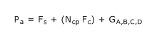
The required axial clamping force for a precision lock nut or the bolts in an end plate can be estimated from
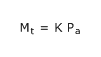
The required tightening torque for a precision lock nut can be estimated from
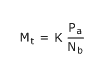
The required tightening torque for end plate bolts can be estimated from
where
Mt Required tightening torque [Nmm]
Pa Required axial clamping force [N]
Fc
Axial fitting force [N]
- For bearings in the 718 .. D, 719 .. D, 70 .. D and 72 .. D series (table 11)
- For bearings in the 719 .. E, 70 .. E and S70 .. W series (table 12)
- For bearings in the 719 .. B and 70 .. B series (table 13)
Fc
minimum axial clamping force [N]
- For bearings in the 718 .. D, 719 .. D, 70 .. D and 72 .. D series (table 11)
- For bearings in the 719 .. E, 70 .. E and S70 .. W series (table 12)
- For bearings in the 719 .. B and 70 .. B series (table 13)
GA,B,C,D Pre-set bearing preload, prior to mounting [N] product table
K Calculation factor dependent on the thread table 14
Ncp Number of bearings in the same orientation as the bearing that the precision lock nut or end plate is in direct contact with1)
Nb Number of end plate bolts
1 This is not the total number of bearings in the arrangement, only those that require to be moved to close gaps between rings to achieve pre-set preload. Refer also to Locking procedure.
Locking procedure
When locating super-precision angular contact ball bearings axially using a precision lock nut or end plate, the following procedure should be applied to be sure that all of the bearings are fully seated and the clamping force is re-set to the estimated required level.
- 1 Tighten the lock nut / end plate bolts 2 to 3 times tighter than the value for Mt.
- 2 Loosen the lock nut / end plate bolts.
- 3 Retighten the lock nut / end plate bolts to the value of Mt.