

 Robert
Pillow Block Bearing Size Chart: How to Determine the Right Size for Your Shaft
The most common sizing mistake we see: someone measures their shaft with a tape measure, rounds to the nearest half-inch, and orders the wrong bore. ...
A linear bearing is only as good as the shaft it runs on.
Pair an LM20UU with an undersized, un-hardened rod and you'll get sloppy motion and early bearing failure.
Pair a THK profiled rail guide with a bent, unmachined extrusion and you'll spend the rest of the project chasing alignment problems.
This guide covers how to select, pair, and size linear bearings with their support rails or shafts — from basic round-shaft systems to profiled rail setups.
If you're still deciding between a round-shaft and profiled rail system, start with our Linear Bearings vs Rotary Bearings overview first.
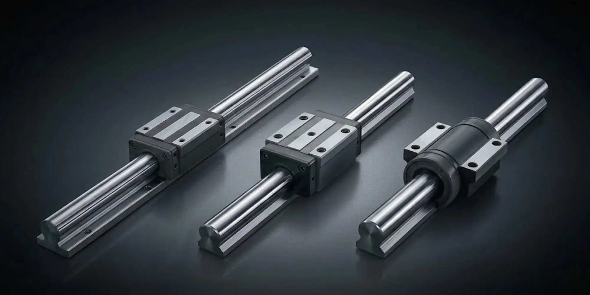
A hardened, ground steel shaft supports one or more bearing blocks or bushings. The bearing has ball elements (or polymer) that ride directly on the shaft OD. This is the simpler, lower-cost system.
Examples:
LMxxUU bearings on Thomson or igus shafting, LM8UU + 8 mm smooth rod in 3D printers.
%20linear%20bearings.webp?width=1000&height=1000&name=Round-shaft%20(cylindrical)%20linear%20bearings.webp)
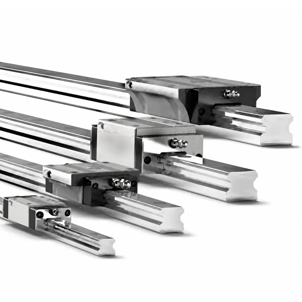
A precision-machined rail with hardened raceways bolted to a flat surface. Carriages with recirculating ball or roller elements run along the rail. This system is stiffer and more precise.
Examples:
THK HSR series, Hiwin HG/EG series, Rexroth STAR series, SBR/SC open-rail systems.
The shaft is the foundation. If it's wrong, nothing else matters.
Material:
The shaft must be hardened steel — minimum 60 HRC surface hardness for precision ball-type bearings.
Standard cold-rolled steel is too soft; ball elements will indent the shaft surface within hours at any meaningful load.
Acceptable shaft types:
Straightness tolerance: Shaft bow should not exceed 0.03–0.05 mm per 300 mm. Most precision-ground shafting meets 0.02 mm/300 mm or better.
Surface finish: Ra 0.2–0.4 μm (8–16 μin) for standard ball bearings.
Diameter tolerance: LMxxUU bearings use an h5 shaft fit — for a 20 mm shaft, that means 19.987–20.000 mm. Oversize = tight fit and high friction. Undersize = play and poor accuracy.
This is where most DIY and entry-level machine designs go wrong. The midspan deflection for a simply supported shaft under a central point load is:
Where: F = load (N) · L = span (mm) · E = 200,000 N/mm² · I = π×d⁴/64 (mm⁴)
This formula assumes worst-case central loading. If the carriage traverses the full span, actual deflection is lower — but always use central loading for conservative design.
Worked example — 20 mm diameter shaft, F = 70 N (2 kg carriage + 5 kg payload), I = 7,854 mm⁴:
Rule of thumb:
keep span-to-diameter ratio under 30:1 for light loads, under 20:1 for anything requiring sub-0.1 mm accuracy. Doubling the span increases deflection by 8× (deflection scales with L³).
Load ratings vary by manufacturer. Always verify against the actual product spec sheet.

One end of the shaft should be fixed (locked against axial movement) and the other should be floating (free to expand thermally).
For a 600 mm steel shaft subjected to a 20°C temperature rise: thermal expansion = 0.6 m × 12 × 10⁻⁶/°C × 20°C = 0.144 mm. If both ends are rigidly clamped, the shaft bows. On a machine with ±0.05 mm accuracy requirements, this matters from day one.
Profiled rail systems use matched rail-and-carriage pairs. The size designator (15, 20, 25, 30, 35, 45 mm) refers to rail width, and carriages are designed for one rail width only:
The short answer: often yes for profiled rail, never for round-shaft bearings.
Major profiled rail brands (THK, Hiwin, NSK, IKO) conform to shared dimensional standards within each size class — mounting hole patterns and carriage envelopes are largely compatible. However, load ratings, preload class, and running fit may differ from a matched-brand pair. For precision applications, buy rail and carriage from the same manufacturer.
Minimum rail length: carriage length + required stroke + 20 mm safety margin.
Rail splice joints: For axes longer than 4 m, joint gap should be ≤0.01 mm. Use manufacturer-supplied precision splice joints.
Use a minimum of 2 carriages per rail whenever moment loads are present. For a cantilever load: Moment M = F × d. Each carriage's moment rating must exceed M/2, with a safety factor of at least 2.0.
Given: 8 kg spindle (78 N), 500 N peak cutting force, 150 mm stroke, ±0.05 mm accuracy, 6 hr/day, 250 days/year.
This extreme result is normal for Z-axes — they accumulate very little travel per day.
The practical limit is lubrication interval and seal condition, not bearing fatigue.
See our Noise & Failure Guide for the maintenance schedule that matters more than this L10 figure.
LM8LUU is the long type — roughly 1.5× the standard length, with an extra ball circuit. Use it when you have cantilevered or offset loads. For straightforward horizontal motion like a 3D printer axis, standard LM8UU is fine.
No. Shaft diameter tolerances and surface hardness specs differ enough between manufacturers that you'll get either binding or slop. Profiled rail is more forgiving — THK, Hiwin, and NSK carriages are dimensionally compatible within the same size class — but for precision work, stick to matched pairs.
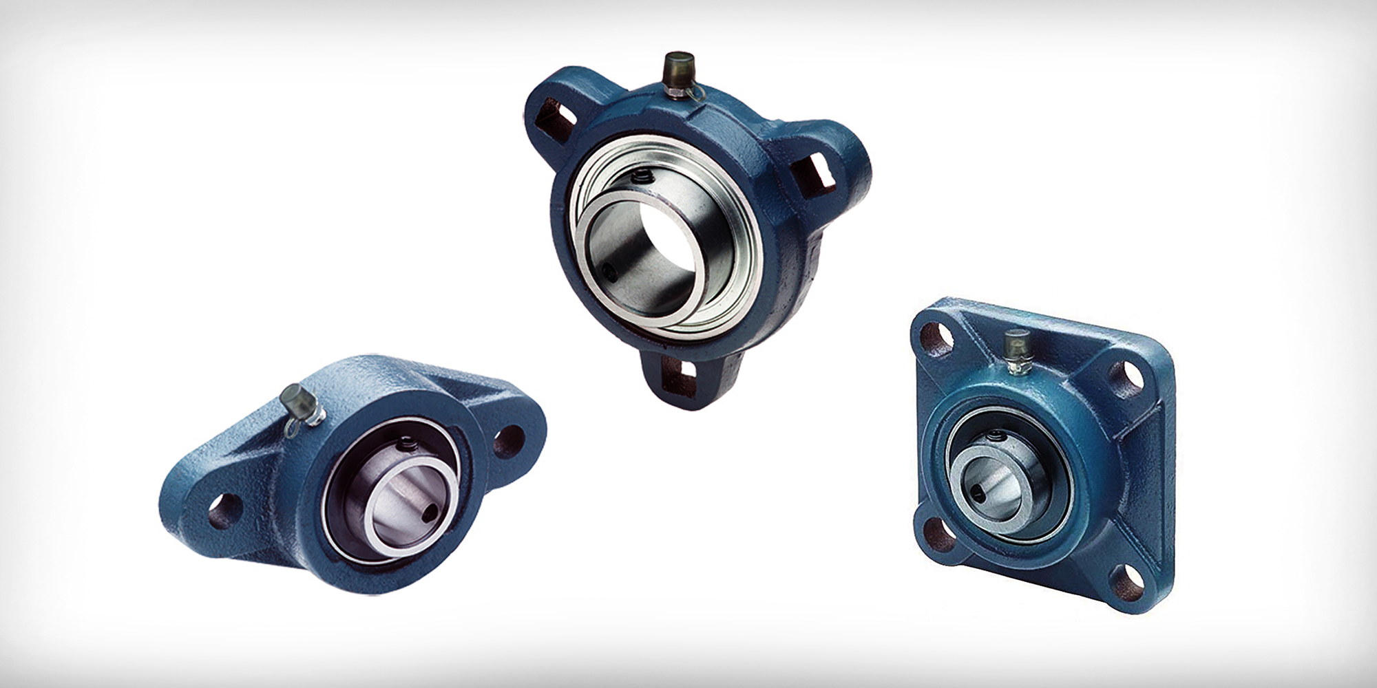
A pillow block is a housing that holds the bearing and gives you bolt-down flanges for easy mounting. The LMxxUU inside is still the same bearing — same shaft requirements, same load ratings. You're just buying the bearing pre-packaged in an aluminum block instead of pressing it into your own housing.
Round-shaft ball bearings (LMxxUU) are typically rated to 1.0–2.0 m/s. Push past that and you get noise, heat, and sharply reduced life. Profiled rail handles 3–5 m/s comfortably. In practice, your drive system — leadscrew, belt — usually becomes the limiting factor before the bearing does.
Check the shaft first. If the surface has visible pitting or you can feel roughness under your fingernail at the ball contact lines, the shaft wasn't hardened. Soft steel (A36, cold-rolled 1018) indents within hours under any real load. Replace the shaft with properly hardened stock — the bearings themselves are usually fine.
The flange lets you push the bearing into a bore from one side and locate it from the other — no retaining ring needed. Useful when you're mounting into thin plate or extrusion profiles where there's no room for circlips. Performance is identical to the standard type.
Before you order:
Need help sizing a specific axis? Share your load, stroke, accuracy, and duty cycle requirements in the comments, and we'll walk through the calculation.
The most common sizing mistake we see: someone measures their shaft with a tape measure, rounds to the nearest half-inch, and orders the wrong bore. ...
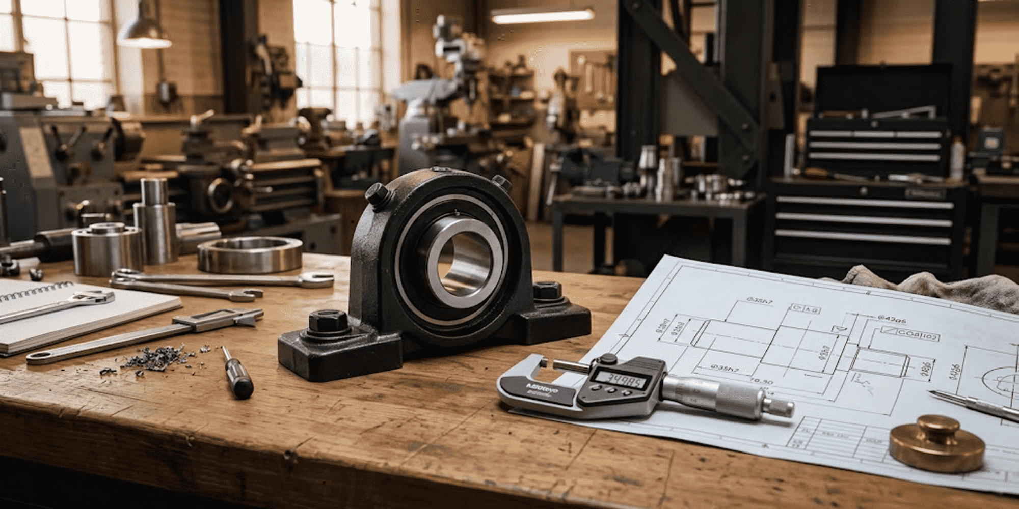
Mounted bearings are essential for industrial machines. They support and stabilize rotating shafts, ensuring they stay aligned and reduce friction. ...
Quick Answer — 8 Steps Clean and inspect the shaft Slide the bearing into position Lightly bolt the housing down Set the final mounting...