

 Richard
Does a Smaller Sprocket Increase Speed?
If you've been riding for a while, you've probably heard someone say "go smaller on the sprocket for more speed" — and walked away wondering: smaller
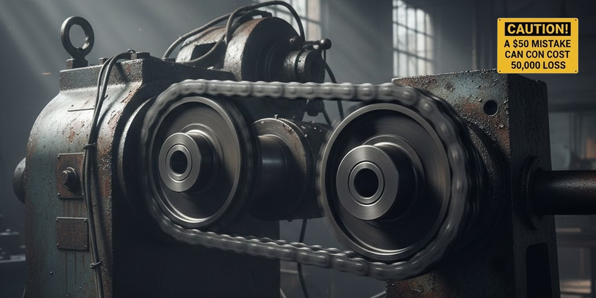
A $50 sprocket mistake can cost you $50,000 in downtime.
Incorrect sprocket selection is the leading cause of premature chain failure.
This single error accounts for 60% of drive system breakdowns in industrial environments.
This guide will show you how to avoid becoming part of that statistic by mastering sprocket types, sprocket ratio selection, and the technical nuances of hub configurations and material science.
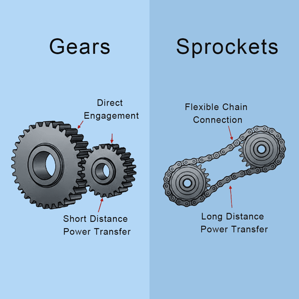
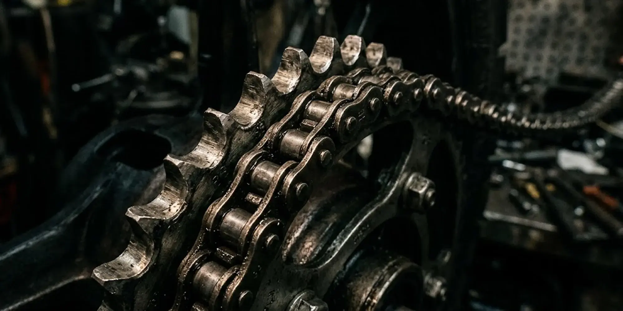
In mechanical engineering, the distinction between sprockets and gears is critical.
While gears mesh directly, sprockets engage a flexible chain to transfer power over distance.
Common Failure Modes:
Calculate the wrong sprocket ratio or use a mismatched pitch, and you'll get 'chordal action'—a pulsating effect caused by chain links entering and exiting the sprocket teeth.
The resulting vibration snaps pins and destroys motor bearings.
To maintain a smooth drive, precision in selection is not an option; it is a requirement.
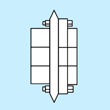
Sprockets are categorized by their hub configuration, which determines how they manage "overhung load"—the lateral force that can bend a drive shaft if the sprocket is positioned incorrectly.
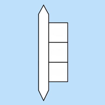
A simple, flat sprocket without any hub thickness.
Because it lacks a hub, Type A is typically bolted directly to a flange or a carrier on the machine. It is the go-to solution when axial space is extremely limited.
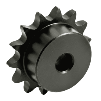
Features a hub on only one side of the plate.
This is the most common configuration in modern machinery. Position the hub side toward the bearing. You'll minimize the load-to-support distance, which reduces 'overhung load' and prevents shaft deflection.
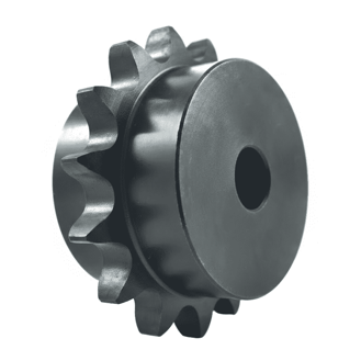
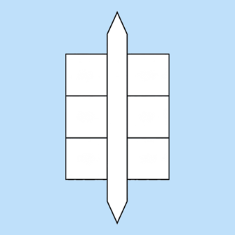
Hubs are integrated onto both sides of the central plate.
Type C is engineered for heavy-duty applications where the sprocket is mounted on larger-diameter shafts. The dual hubs provide a greater contact surface area for the keyway and set screws. This keeps the sprocket locked tight during high-torque reversals.
Often features an uneven or split-body design.
This is a strategic choice for high-stakes production lines. A split hub (Type D) allows you to "clamp" the sprocket onto the shaft at any point. You won't need to disassemble other components like bearings or couplings. This design reduces downtime—turning a four-hour repair into a 20-minute adjustment.
Expert engineers follow the "17-Tooth Rule."
While sprockets can have as few as 9 teeth, using fewer than 17 teeth increases vibration and noise significantly.
Additionally, consider the Hunting Tooth Advantage.
Using an even-numbered ratio (e.g., 20/40) means the same chain link hits the same sprocket tooth every cycle, accelerating wear patterns.
Choosing odd numbers (e.g., 19/41) ensures the links "hunt" for new teeth, distributing wear evenly across the entire set.

The material must survive the operating environment.
A $50 sprocket is worthless if it corrodes and snaps in a month.
Hardened Carbon Steel: The industry standard. Inductive tooth hardening (HRC 40-50) is mandatory for drives exceeding 500 RPM.
Stainless Steel (304 or 316): Essential for food processing (FDA compliance). Note that stainless has lower load-bearing limits than carbon steel.
Thermal Expansion & Pitch: In extreme temperatures (e.g., blast freezers at -40°C or ovens at 200°C), metal expands and contracts. This changes the effective pitch. In these cases, we recommend a slightly larger "clearance" tooth profile to prevent the chain from binding.
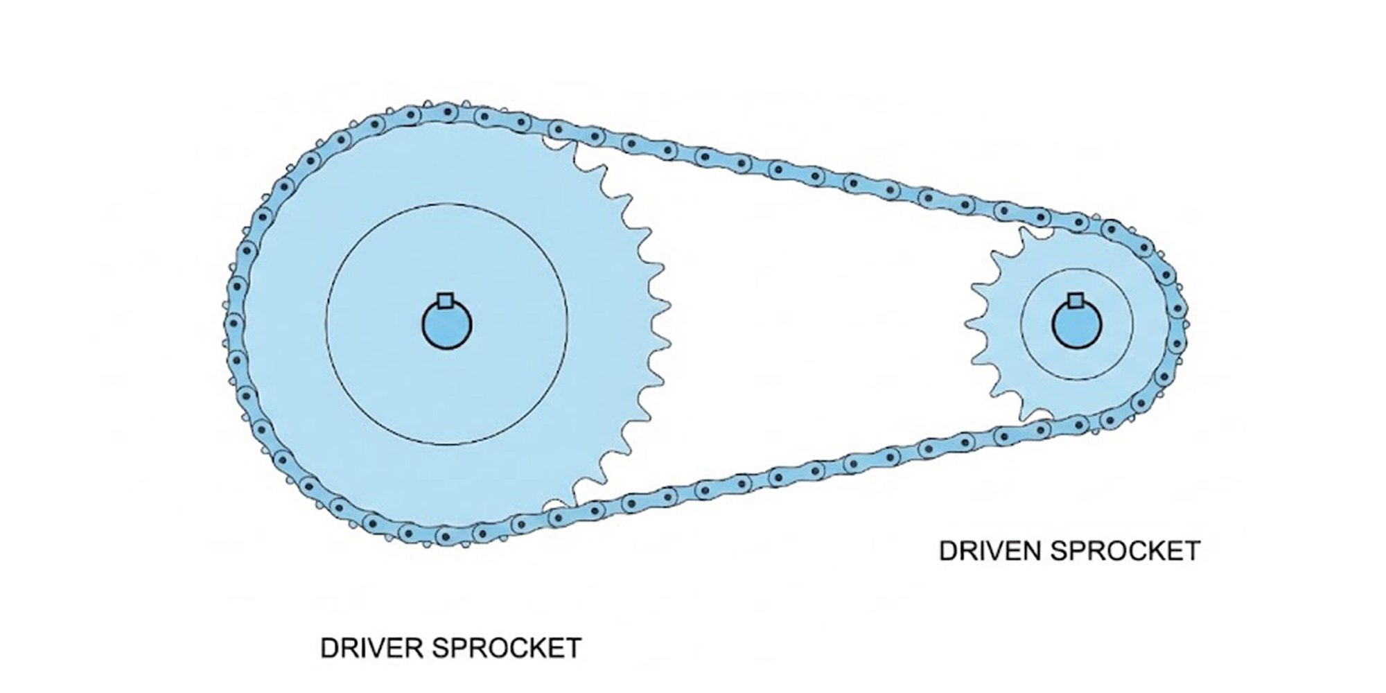
The sprocket gear ratio determines the balance between torque and velocity. Use this logic to optimize your machinery.
The "1-Tooth Rule":
Changing just one tooth on the small drive sprocket has a much larger impact than changing one on the large driven sprocket.
A 1-tooth change on the front is typically equivalent to a 3-to-4 tooth change on the rear.
High-Speed Packaging Example:
If your drive motor runs at 1800 RPM with a 21T sprocket and the driven head has 14T, the packaging head will run at 2,690 RPM for rapid-fire sealing operations.
Shaft spacing is critical for chain health. If the distance is too short, the chain won't wrap enough teeth; too long, and it will whip.
Optimal spacing for most industrial drives is 30 to 50 times the chain pitch.
Example: For an ANSI 60 chain (0.75" pitch), the ideal center distance is between 22.5" and 37.5".
Minimum Wrap: Ensure the chain wraps at least 120° around the small sprocket. If you cannot achieve this, an Idler Sprocket must be placed on the slack side of the chain to maintain tension.
Even 1 degree of misalignment reduces chain life by 50%.
Use a laser alignment tool or a precision straightedge to verify that your shafts are perfectly parallel.
Never mix ANSI (American) and BS (British/European) standards.
An ANSI 40 sprocket and a 08B chain may look identical, but the tooth profiles differ, causing the chain to "climb" and jump.
Optimal tension is a 1-2% sag of the span distance.
A chain that is too tight will destroy the bearings; a chain that is too loose will jump teeth under load.
The "Hook" Profile: If teeth look like a shark's fin or are "hooked," they are pulling the chain rollers. Replace them immediately.
Calipe Diameter: Missing or worn teeth make counting impossible. In this case, measure the Caliper Diameter (the plate diameter between teeth) to find the correct replacement.
Lubrication: High-speed drives require continuous oil baths or drip systems. For slow drives, manual lubrication every 8 hours is the industry standard.
You now know how to select sprockets correctly: match hub types, calculate ratios, ensure pitch compatibility, and manage loads.
Master these, and you'll avoid the 60% failure rate.
Lily Bearing turns this knowledge into performance with five precision sprocket lines:
ANSI Roller Chain Sprockets (Inch) – for standard industrial drives
Metric Roller Chain Sprockets – for global metric chain systems
Miniature Roller Chain Sprockets – for precision compact machinery
Idler Sprockets – for tensioning and system support
Bushing-Bore Sprockets – for flexible shaft mounting
All meet ISO, ANSI, and DIN standards. Engineer uptime. Choose Lily Bearing.
If you've been riding for a while, you've probably heard someone say "go smaller on the sprocket for more speed" — and walked away wondering: smaller
In any power transmission setup, the relationship between the chain and the sprocket is symbiotic. While much attention is often given to chain...
In roller chain drive systems, the number of teeth on the sprocket is important. It affects how well the system works. No matter what type of machine...