

 Richard
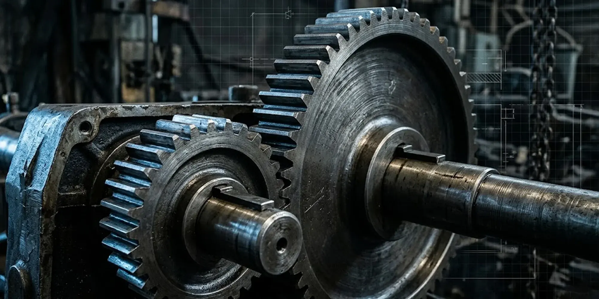
What Are Worm Gears? Types, Ratio, Mechanism & Applications
Worm gears are everywhere in daily life. You'll find them in car steering systems, conveyor belts, and stand mixers—often working invisibly behind...
Quick answer: Gear ratio = driven gear teeth ÷ drive gear teeth. A 60-tooth driven gear meshed with a 20-tooth drive gear gives a 3:1 ratio — one output rotation per three input rotations, at three times the torque.
The fundamental relationship is straightforward:
Where Tdriven is the tooth count on the output gear and Tdrive is the tooth count on the input gear. The same ratio applies to shaft speeds:
And to torque — applying an efficiency factor:
No real gearbox runs at 100% efficiency.
Spur gears typically hit 96–99%; worm gear sets can fall to 50–90% depending on lead angle.
Always apply an efficiency factor before sizing your motor.
The American Gear Manufacturers Association (AGMA) publishes standardized efficiency ratings for each gear type.
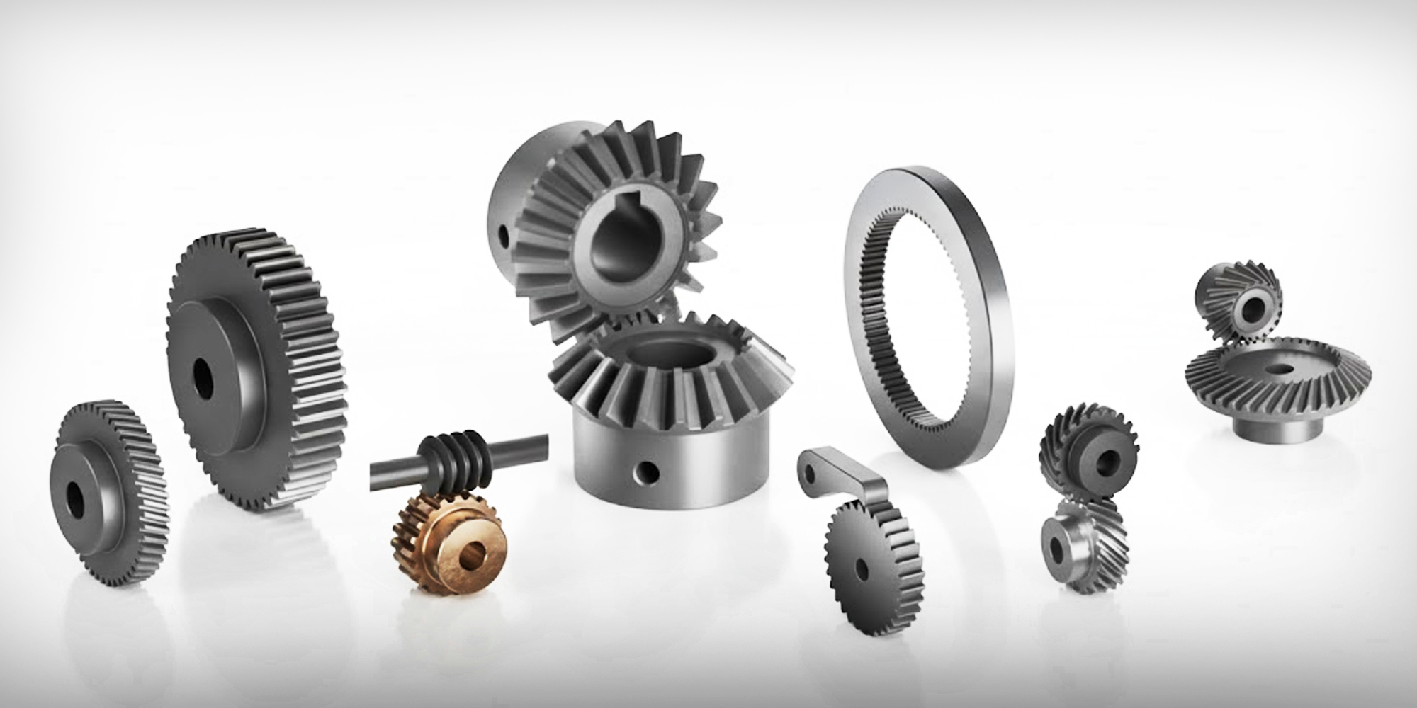
Each gear configuration has a practical ratio range. Working outside it usually means you are using the wrong gear for the job.

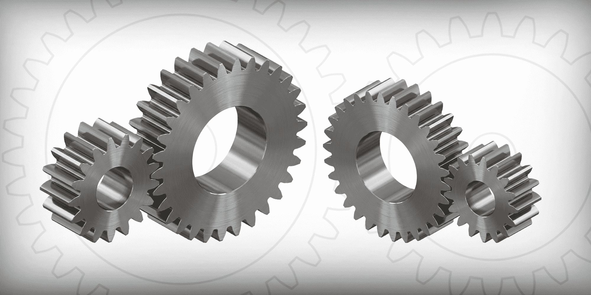
Straight-tooth cylindrical gears — the most common choice for parallel shafts.
A single spur stage handles ratios from 1:1 up to about 6:1; multi-stage arrangements push that to 20:1.
Efficiency sits at 96–99%, making spur gears the default for conveyors, machine tools, and packaging lines where noise is not a constraint.
→ Browse Spur Gears
Angled teeth engage progressively rather than all at once — cutting vibration and noise significantly at the same pitch-line velocity, while maintaining 96–99% efficiency.
Practical ratio range is 3:1 to 10:1 per stage.
Automotive transmissions, compressors, and high-speed industrial drives favor helical gears when quiet operation matters.
→ Browse Helical Gears
Bevel gears redirect power between intersecting shafts — most often at 90°.
Miter gears are a special case: equal tooth counts on both gears, giving a 1:1 ratio at the angle change.
Standard bevel pairs cover 1:1 to 6:1 at 93–97% efficiency.
Right-angle conveyors, differential drives, and hand tools are typical applications.
→ Browse Miter Gears and Bevel Gears
A screw-form worm drives a worm wheel at 90°.
The geometry allows ratios from 5:1 to 300:1 in a single compact stage — no other gear type matches that range without stacking multiple stages.
The trade-off is efficiency: 50–90%, dropping sharply as ratio increases.
Above roughly 20:1, most worm sets become self-locking, meaning back-driving from the output side is impossible without a separate input.
That built-in holding capability eliminates the need for an external brake in lifting equipment and packaging machinery.
→ Browse Worms and Worm GearsThree or more planet gears share the load simultaneously around a central sun gear — the highest torque density of any gear arrangement. Efficiency reaches 97–99% per stage.
Single-stage planetary units cover 3:1 to 10:1; stacked two-stage units reach 100:1.
Robotics, servo axes, wind turbines, and precision automation rely on planetaries where compactness and high efficiency are both required.

Picking the right ratio takes four numbers: required output speed, required output torque, available input speed, and available input torque.
|
1
|
Define output requirements. Work backward from the machine. A conveyor belt running at 0.5 m/s with a 200 mm drive drum needs the drum shaft at (0.5 ÷ (π × 0.2)) × 60 ≈ 47.7 RPM. |
|
2
|
Know your motor speed. A standard 4-pole induction motor at 60 Hz runs at 1,720–1,760 RPM. A servo motor might peak at 3,000 RPM. Use nameplate data, not nominal values. |
|
3
|
Calculate the required ratio. GR = Input RPM ÷ Required output RPM. Using the conveyor example with a 1,460 RPM motor: GR = 1,460 ÷ 47.7 = 30.6:1. A standard 30:1 or 31:1 gearbox fits — achievable in a single worm stage, or two helical stages in series. |
|
4
|
Check torque. Verify that output torque at the selected ratio covers your load, with a service factor applied. Most industrial drives use a service factor of 1.25 to 2.0 depending on shock loading conditions, per AGMA guidelines. |
When one gear pair cannot reach the required ratio, stages are arranged in series. The total ratio multiplies across stages:
This is why planetary stages are often stacked: two 5:1 stages give 25:1, three give 125:1, all inline without the efficiency penalty of worm-on-worm arrangements.
All three terms describe the same physical relationship — expressed from different starting points:
| Term | Formula | Context |
|---|---|---|
| Gear ratio | T_driven ÷ T_drive | Gear design and selection |
| Speed ratio | RPM_input ÷ RPM_output | Shaft speed calculations |
| Torque ratio | Torque_out ÷ Torque_in | Drive sizing (at 100% efficiency) |
A 5:1 gear ratio means 5 input rotations per output rotation, one-fifth the speed, and (at 100% efficiency) five times the torque. In practice, subtract gearbox losses from that torque figure.
| ⚠️ |
Skipping efficiencyA worm gearbox at 50:1 and 70% efficiency delivers 50 × 0.70 = 35× your input torque — not 50×. Size your motor for actual output, not theoretical maximum. |
| ⚠️ |
Ignoring inertia matchingIn servo and stepper systems, the reflected load inertia (load inertia ÷ GR²) should ideally land within 1:1 to 10:1 of motor rotor inertia. A mechanically correct ratio with a 50:1 inertia mismatch causes overshoot and slow settling times. |
| ⚠️ |
Over-stagingEvery gear stage adds cost, backlash, weight, and efficiency loss. If a single 30:1 worm stage meets the requirement at adequate efficiency, a three-stage spur train is the wrong answer. |
| ⚠️ |
Designing around ideal ratiosStandard gearboxes come in preferred ratio steps: 5, 7, 10, 15, 20, 25, 30, 40, 50. Design the system to accept available ratios rather than chasing a calculated ideal that does not exist in a catalog. |
Need the Right Gear for Your Ratio?
Browse our full range of precision gears — spur, helical, bevel, worm, and more — with detailed specs and immediate availability.
Browse All Gears Shop Gearmotors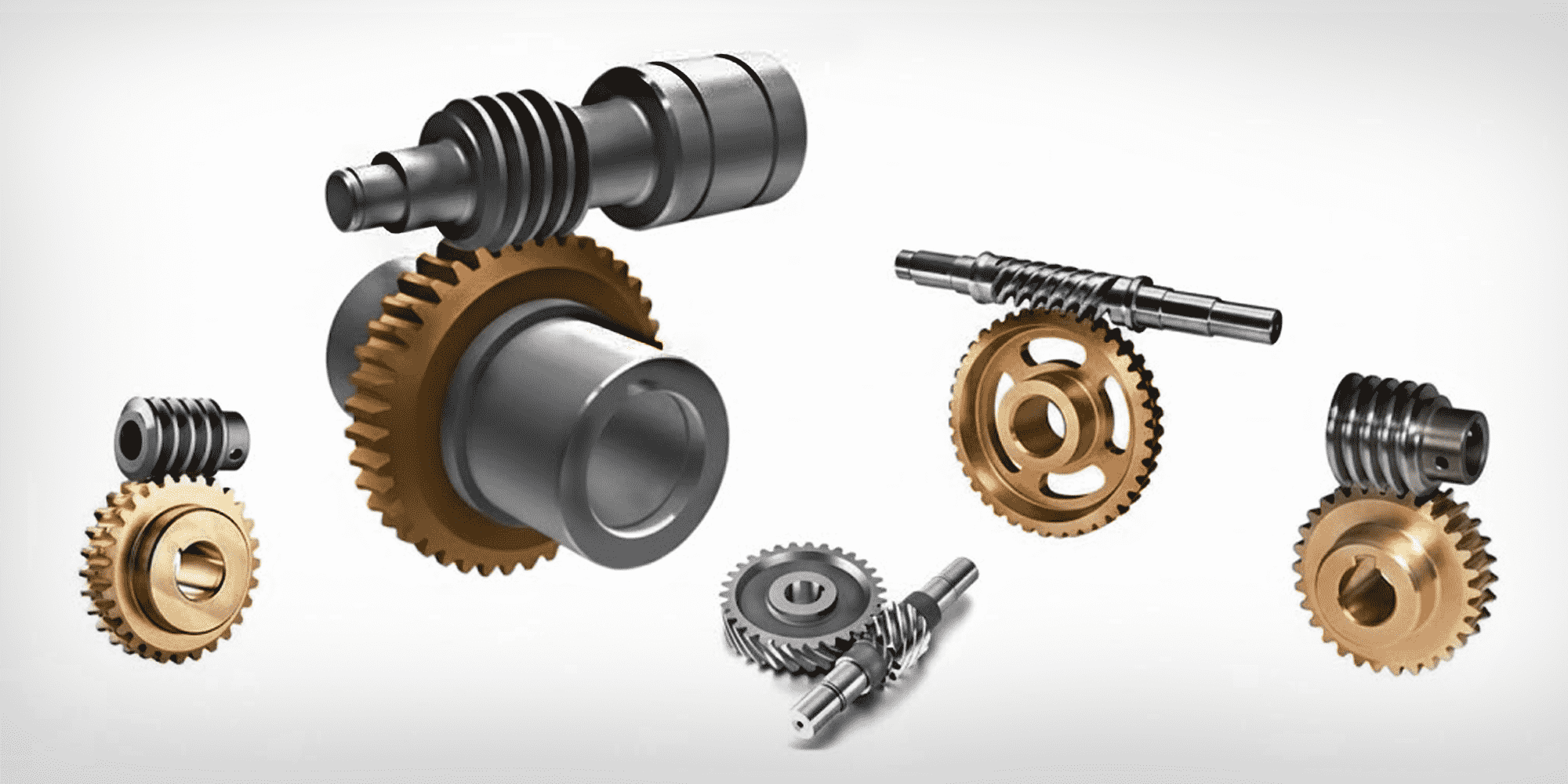
Worm gears are everywhere in daily life. You'll find them in car steering systems, conveyor belts, and stand mixers—often working invisibly behind...
Gears remain fundamental components in mechanical systems worldwide, transferring motion and power between rotating shafts. Knowing which gear to...
Walk into any factory, open up a household appliance, or look inside a medical device, and you'll almost certainly find a spur gear doing quiet,...