

 Richard
What Are Spur Gears? Types, Design, Uses & How to Choose the Right One
Walk into any factory, open up a household appliance, or look inside a medical device, and you'll almost certainly find a spur gear doing quiet,...
Gear backlash is one of those variables that separates a well-engineered drive system from one that drifts, rattles, or wears out ahead of schedule.
It shows up in CNC machines, robotic joints, automotive differentials, and industrial gearboxes — and yet it's routinely misunderstood, either ignored until something goes wrong or over-corrected in ways that cause different problems.
This article covers what backlash actually is, where it comes from, what it does to your system, and how to bring it within spec.
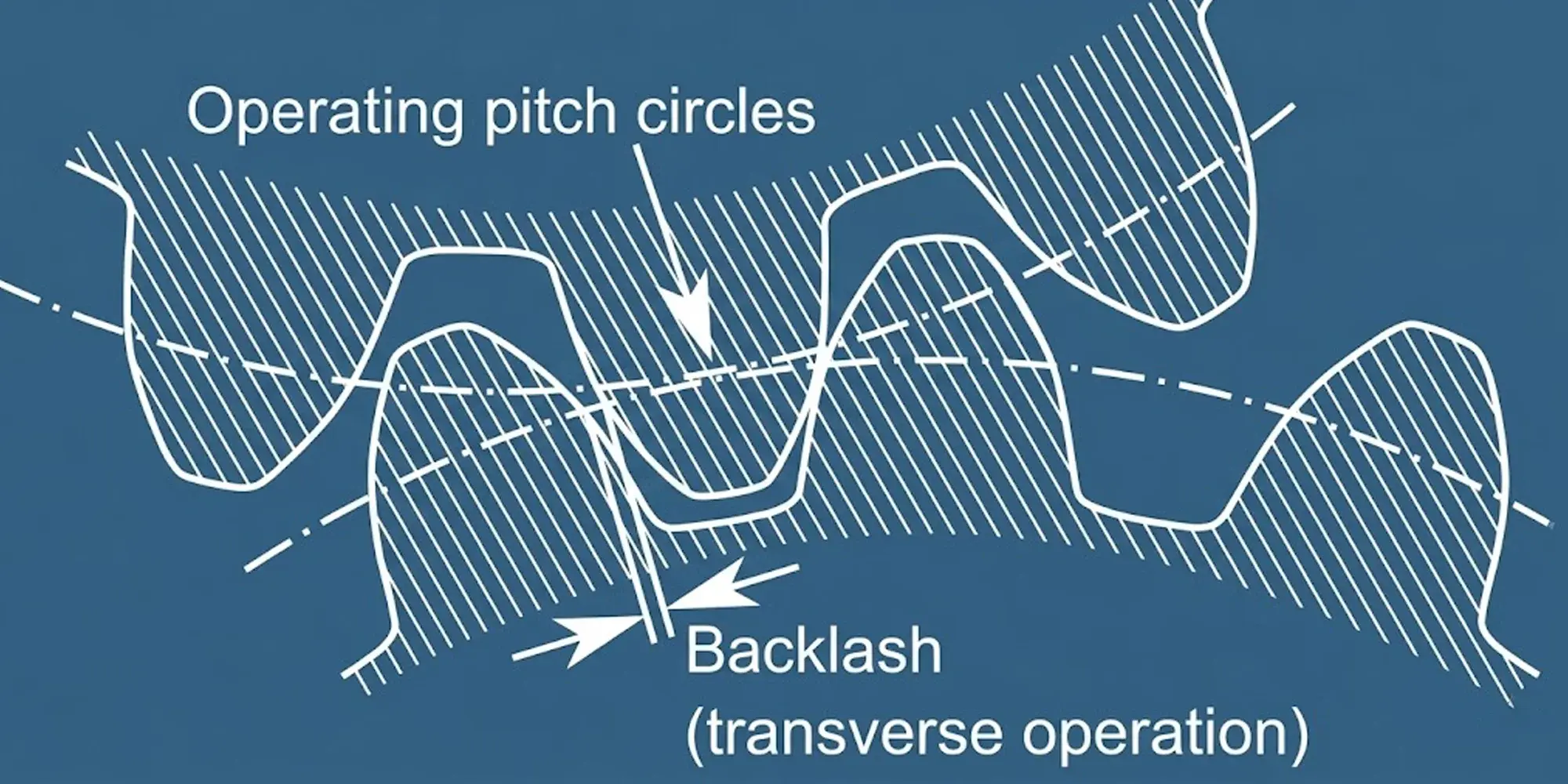
Backlash is the amount of free angular movement between two meshing gears when one gear is held stationary and the other is rotated back and forth without transmitting load.
In simpler terms: it's the gap between the non-driving flanks of mating gear teeth.

It's typically measured in one of two ways:
Linear backlash
The gap at the pitch circle, expressed in millimeters or thousandths of an inch.
Angular backlash
The corresponding rotation of the output shaft, expressed in arc minutes (1 arc minute = 1/60°).
For precision planetary gearboxes, backlash specs commonly run from under 1 arc minute (ultra-precision) to around 3–5 arc minutes (standard grade).
A spur gear pair in general industrial use might have 0.05–0.3 mm of linear backlash depending on module and center distance.
Backlash is not the same as runout, tooth profile error, or pitch deviation — though all of these affect how a gear system actually performs.
No backlash is manufactured into a gear system by accident. It exists for three legitimate engineering reasons.
Even with CNC gear hobbing and grinding, tooth thickness varies by a few microns.
Two gears meshed with zero theoretical backlash would bind as soon as tolerance stack-up pushed any tooth slightly oversized.
Carbon and alloy steels expand at approximately 11–13 µm per meter per °C, depending on alloy and heat treatment.
A gearbox running at 60°C above ambient will see measurable growth in tooth thickness and center-to-center distance.
Backlash provides the clearance that prevents thermal seizure.
Oil or grease between gear teeth requires physical space to form a hydrodynamic film.
Eliminate backlash completely and you starve the contact zone, accelerating wear and surface fatigue.
The engineering goal is never "zero backlash" — it's minimum backlash consistent with operating conditions.
Excessive backlash — beyond the designed tolerance — is a different problem. It usually develops through one or more of these paths:
Every engagement cycle removes a small amount of material from gear flanks.
In high-cycle applications without adequate lubrication, this wear compounds quickly.
A gear pair running at 1,000 RPM logs 525 million cycles in a single year; even microscopic per-cycle wear accumulates.
Moving gear centers apart by just 0.1 mm can add several hundredths of a millimeter of backlash, depending on the pressure angle.
On 20° pressure angle gears, a 0.1 mm increase in center distance adds approximately 0.073 mm of backlash.
Worn bearings allow shaft deflection, which effectively changes the operating center distance under load — producing backlash that appears intermittent and load-dependent.
Inadequate preload on tapered roller bearings, incorrect shim thickness in bevel gear sets, or misaligned housing bores all create backlash beyond design intent.
In motion control applications — CNC machining centers, robot arms, coordinate measuring machines — backlash directly limits positioning repeatability.
When a drive axis reverses direction, the motor must first take up the backlash before the output moves.
During that lost motion, the control system receives no position feedback, or worse, incorrect feedback.
A 3 arc-minute backlash on a planetary gearbox driving a ballscrew through a 10:1 gear ratio produces 0.3 arc minutes of output error — small, but significant for sub-0.01 mm positioning requirements.
CNC compensation routines can partially correct for backlash, but software compensation works best when backlash is consistent and below about 0.05 mm.
Variable backlash — from worn teeth or loose bearings — defeats compensation entirely.
Backlash creates impact loading every time gear tooth contact reverses.
As load direction changes, the previously unloaded flank suddenly comes into contact with momentum behind it.
The result is a distinct knocking or rattling sound, particularly noticeable at light loads where the gear teeth are not held firmly in mesh by torque.
In automotive differentials and transfer cases, this manifests as the familiar "clunk" felt when transitioning from acceleration to deceleration.
In high-speed gearboxes, cyclic tooth impact generates vibration at tooth mesh frequency and its harmonics, which can excite resonances in the structure.
Impact loading from backlash is not just noisy — it concentrates stress.
Hertzian contact stress spikes during tooth impact can be several times the steady-state value.
Over time, this causes pitting, spalling, and eventually tooth fracture, particularly at the root fillet where bending stress is highest.

In reversing or oscillating applications, energy is lost to the impact of teeth re-engaging across the backlash gap.
This is generally a minor efficiency loss in continuous-rotation systems but becomes significant in positioning systems that make frequent small bidirectional moves.
Before adjusting anything, measure. There are three standard methods:
For high-precision applications, laser interferometers and rotary encoders on both input and output shafts allow dynamic backlash measurement under realistic operating conditions.
Specifying a higher AGMA or ISO gear quality class tightens tooth thickness tolerance directly.
AGMA Quality 11 gears hold tooth thickness tolerances roughly twice as tight as Quality 9.
The cost premium is real — expect 30–50% higher gear costs for a two-grade improvement.
For spur and helical gears, reducing center distance closes the backlash.
This is the simplest adjustment for an assembled gearbox: replace shims or adjust bearing housings to bring centers closer.
The relationship is approximately linear with pressure angle.
Helical gears with opposite hand can be paired on a common shaft (scissors gear / duplex gear arrangement), with one half preloaded against the other.
This eliminates backlash entirely in the circumferential direction at the cost of constant axial preload force on bearings.
One gear is split into two halves, spring-loaded circumferentially against each other.
Both halves maintain contact with the mating gear simultaneously, eliminating backlash regardless of direction — the same principle behind anti-backlash gears used in instrument gearing, rack-and-pinion positioning systems, and camera/telescope drives.

When specifying gearboxes for motion control, backlash is typically defined at rated output torque with no input rotation.
Key specs to compare:
Harmonic drives (strain wave gearing) achieve near-zero backlash through a fundamentally different engagement principle — simultaneous contact across many teeth rather than point contact between two — making them the standard choice for collaborative robot joints and precision actuators.
Backlash should be measured at scheduled intervals and trended over time.
A sudden step change in measured backlash typically indicates bearing failure or a broken tooth.
Gradual increase over hundreds of hours reflects normal wear.
Many modern servo drives can estimate backlash continuously through position error analysis: the difference between command position and encoder feedback during direction reversals.
This allows condition-based maintenance rather than fixed intervals.
For general-purpose spur gears, AGMA 2002 provides recommended backlash ranges based on module and center distance.
As a reference, typical values for normal backlash (millimeters of linear backlash):
| Module (mm) | CD ≤ 50 mm | CD 50–125 mm | CD 125–250 mm |
|---|---|---|---|
| 1 | 0.06–0.09 | 0.07–0.11 | — |
| 2 | 0.08–0.12 | 0.10–0.15 | 0.12–0.18 |
| 3 | 0.10–0.15 | 0.12–0.18 | 0.15–0.22 |
| 5 | 0.13–0.20 | 0.16–0.24 | 0.19–0.29 |
CD = center distance. Source: AGMA 2002.
These are starting points, not absolutes.
High-speed applications, elevated operating temperatures, or heavily loaded gearboxes may require values toward the upper end.
Precision positioning applications should work from the specific gearbox manufacturer's tolerance document rather than general tables.
More common than people expect, particularly after a rebuild.
Insufficient backlash causes the teeth to run hot, accelerates surface wear, and can seize the mesh in thermal transients.
If a freshly rebuilt gearbox runs hotter than the original, check backlash first.
Field Case
One case we encountered: a 5-axis machining center returned from a spindle rebuild with an intermittent thermal alarm. The gearbox temperature would climb past 85°C within 90 minutes of startup and trigger an automatic shutdown. The rebuilt gear set had been assembled 0.04 mm tighter than the original — within what the technician considered acceptable tolerance — but that margin was enough to cause boundary lubrication failure at operating temperature. Reopening to the correct backlash range resolved the issue without replacing any parts.
Replacing gears without inspecting bearings, or adjusting backlash without addressing worn bearings, produces measurements that change under load.
The gearbox appears correctly set on the bench and exhibits backlash in service.
Backlash compensation in CNC controllers works within a narrow range and degrades as backlash becomes variable.
It's a bridge to the next maintenance window, not a substitute for mechanical correction.
Walk into any factory, open up a household appliance, or look inside a medical device, and you'll almost certainly find a spur gear doing quiet,...
Quick answer: Gear ratio = driven gear teeth ÷ drive gear teeth. A 60-tooth driven gear meshed with a 20-tooth drive gear gives a 3:1 ratio — one...
The world's leading gear manufacturers and power transmission manufacturers are the cornerstone of industrial growth, enabling everything from...