

 Robert
Needle Roller Bearing Size Chart: Dimensions, Tolerances & Selection Guide
Needle roller bearings pack a high load capacity into a radial cross-section that can be 3–4 mm thin. That combination of small envelope and strong...
Slewing bearings handle some of the most demanding rotational loads in engineering — crane jibs, wind turbine nacelles, excavator upperstructures.
Getting the torque right is not optional.
Underestimate it and the drive system stalls or fails; overestimate it and you overspec expensive hardware.
This guide walks through what slewing bearing torque actually means, which variables move the needle, and how to calculate it with enough precision for real applications.

Torque is the rotational equivalent of linear force.
In the context of slewing bearings, it is the twisting force required to initiate or sustain rotation against all resisting loads — friction between rolling elements and raceways, preload forces, seal drag, and any moment loads acting on the bearing.
The standard expression is:
τ = F × r
where τ is torque (Nm), F is the applied rotational force (N), and r is the perpendicular distance from the axis of rotation to the point of force application (m).
In practice, two torque values matter for any slewing bearing application:
|
Starting Torque Higher Overcomes static friction Typically 30–50% above running torque Drive motor must be sized for this peak |
Running Torque Lower Sustains rotation at speed Reduced by kinetic friction and film lubrication Used for power consumption estimates |
Both values must be calculated before specifying a drive system.
Sizing the motor only to running torque is one of the most common — and costly — design errors in slewing bearing applications.
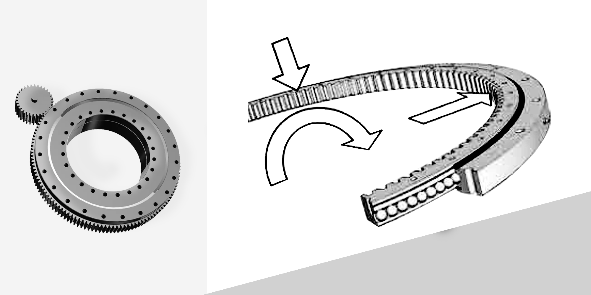
Slewing bearings — also called turntable bearings or slewing rings — are large-diameter bearings designed to handle simultaneous axial, radial, and moment loads while permitting full 360° rotation.
Understanding how each component contributes to torque helps diagnose inefficiency and select the right configuration.
Three load types act on a slewing bearing simultaneously, and each contributes to friction torque in a different way:
|
Axial Load ↓ Parallel to rotation axis (vertical in most cranes) Effect on torque: Increases contact normal force → raises friction torque linearly |
Radial Load → Perpendicular to axis (horizontal shear) Effect on torque: Creates uneven stress distribution; large radial loads require crossed roller design |
Tilting Moment ↻ Overturning bending force about a diameter Effect on torque: Most demanding load type; drives raceway deformation and sharp torque increases |
Tilting moments deserve special attention.
A crane jib carrying 10 tonnes at 8 meters from the bearing center generates an overturning moment of 800 kNm — far exceeding the axial load contribution.
Bearing manufacturers publish moment capacity ratings; exceeding them even briefly accelerates raceway spalling.
For a detailed breakdown of how to calculate and manage this load type, see our guide on the tilting moment of a slewing bearing.
Friction is the primary source of resistive torque in any slewing bearing. The friction torque component can be estimated as:
Mf = μ × Ftotal × d/2
where μ is the effective friction coefficient, Ftotal is the combined resultant bearing load (N), and d is the rolling element pitch diameter (m).
Typical friction coefficients under well-lubricated conditions:
| Bearing Type | μ (well-lubricated) | μ (poor lubrication) |
|---|---|---|
| Four-point contact ball | 0.004 – 0.006 | 0.008 – 0.015 |
| Crossed roller | 0.003 – 0.005 | 0.007 – 0.012 |
| Three-row roller | 0.005 – 0.008 | 0.010 – 0.018 |
Inadequate lubrication can double or triple friction torque within hours of operation.
Most manufacturers specify re-greasing intervals of 100–300 operating hours, though heavily loaded or outdoor installations typically require the shorter end of that range.
Over-lubrication is also detrimental — excess grease causes churning resistance and elevated operating temperatures.
The rolling element geometry, raceway curvature, and material hardness all influence the contact area and therefore friction torque.
Harder materials with tighter tolerances produce lower and more predictable torque.
Common material options:
| Material | Typical Hardness (HRC) | Best For | Limitation |
|---|---|---|---|
| Bearing steel (52100) | 58 – 64 | High load, high cycle | Corrosive environments |
| Stainless steel (440C) | 55 – 60 | Marine, food processing | Lower load capacity vs. 52100 |
| Silicon nitride ceramic | ~78 (Vickers equivalent) | High-speed, high-temp | Brittle; high cost |
| Bronze | ~25 – 35 | Moderate loads, vibration | Regular lubrication required |
| PEEK / polymer | — | Low load, corrosive media | Not for heavy loads or high speed |
A slewing bearing installed on a mounting surface with more than 0.1 mm/m flatness deviation can experience load concentration at just a fraction of its rolling elements — dramatically increasing local contact stress and friction torque.
Common installation errors and their torque consequences:
| Installation Issue | Effect on Torque |
|---|---|
| Surface flatness deviation >0.1 mm/m | Uneven load distribution; torque spikes during rotation |
| Incorrect preload setting | Increased baseline friction torque |
| Non-uniform bolt torquing | Ring distortion; binding at specific rotational positions |
| Damaged or missing seals | Contaminant ingress; accelerated friction increase |
| Wrong installation direction | Misalignment of gear mesh; increased drive torque requirement |
There is no single universal formula because torque depends on the load combination, bearing geometry, and friction state.
The three most practical approaches are:
① Power Method
M = P / ω
Use when motor power and rotational speed are known. P in watts; ω in rad/s; M in Nm.
② Inertia Method
M = J × α
Use during acceleration phases. J = moment of inertia (kg·m²); α = angular acceleration (rad/s²). Critical for sizing drives that must ramp up speed quickly.
③ Force-Lever Method
M = F × L
Use when load and offset distance are the primary knowns. F in newtons; L in meters. Most direct method for crane and excavator applications.
The following example calculates the slewing torque for a crane rotating its jib through 360°.

For heavy-duty or dynamic applications, manual formulas provide an estimate but not a final answer.
Finite element analysis (FEA) and dedicated bearing simulation software from manufacturers account for factors such as dynamic load cycling, thermal expansion effects, manufacturing tolerances, and raceway contact fatigue life — none of which are captured by static torque equations alone.
Torque performance degrades predictably with use.
Most slewing bearing failures are not sudden — they follow a traceable deterioration path that regular maintenance can intercept.
According to ISO 76 and related standards, bearing service life calculations assume adequate lubrication is maintained throughout.
Deviating from that assumption voids the rated life estimate.
Replacement is warranted when any of the following occur:
running torque increases by more than 25% from the baseline established at commissioning;
raceway spalling or flaking is visible during inspection;
radial play exceeds manufacturer limits (typically 0.3–1.0 mm depending on bearing diameter);
or vibration analysis reveals characteristic ball/roller pass frequencies at elevated amplitude.
Continuing to operate beyond these thresholds does not extend useful life — it accelerates catastrophic failure and risks equipment damage that far exceeds the cost of a planned bearing replacement.
Slewing bearing torque is the rotational force required to initiate or maintain rotation against all resisting forces — including friction, load-induced moments, and preload. It is expressed in newton-meters (Nm) and has two distinct values: starting torque (higher, to overcome static friction) and running torque (lower, to sustain rotation).
The most practical formula is M = P / ω (motor power ÷ angular velocity in rad/s). For load-based calculations use M = F × L (force × lever arm). Always multiply by the bearing efficiency factor (typically 0.85–0.95) to get actual output torque. Also calculate starting torque separately — it is typically 30–50% higher than running torque.
The tilting moment (overturning moment) is a bending force that tries to tip the bearing off its rotational axis, caused by offset loads — for example, a crane jib carrying a load horizontally away from the bearing center. It is expressed in kNm and must stay within the bearing's rated moment capacity to prevent raceway deformation and accelerated wear.
For four-point contact ball slewing bearings under ideal lubrication, the effective friction coefficient (μ) typically ranges from 0.004 to 0.006. Crossed roller designs run slightly lower at 0.003–0.005. These values can double or more under misalignment or inadequate lubrication — which is why lubrication maintenance directly impacts torque performance.
Starting torque is the peak force needed to break static friction and initiate rotation — always higher than running torque, often by 30–50%. Running torque is the sustained force to maintain rotation at speed. Sizing the drive motor only to running torque is a common design error that leads to stall during startup, especially under load.
Proper lubrication forms a film between rolling elements and raceways that reduces friction torque. Insufficient grease increases friction torque by 20–40% and accelerates raceway wear. Over-lubrication causes churning losses that also raise operating torque and temperature. Most manufacturers specify re-greasing every 100–300 operating hours, with shorter intervals for heavy or outdoor applications.
Slewing bearing torque is not a single fixed number — it varies with load combination, friction state, speed, and alignment. Always calculate both starting and running torque, account for bearing efficiency (0.85–0.95), and add margins for dynamic and environmental loads before specifying drive components.
Proper lubrication remains the single highest-impact maintenance action for sustaining rated torque performance over the bearing's service life. A bearing maintained to spec will deliver predictable torque throughout its design life. One that is neglected will not — and the failure mode is rarely convenient.
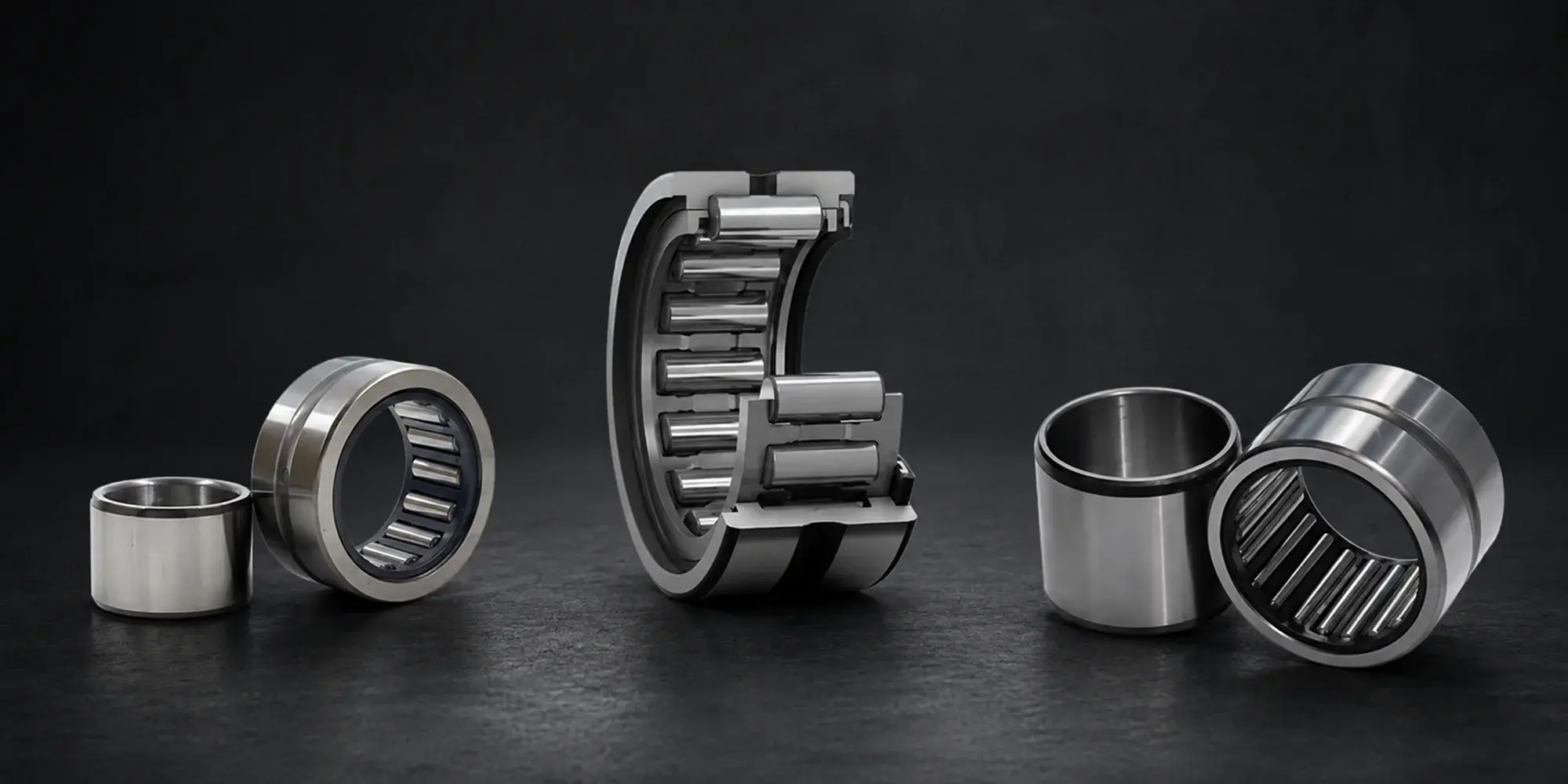
Needle roller bearings pack a high load capacity into a radial cross-section that can be 3–4 mm thin. That combination of small envelope and strong...
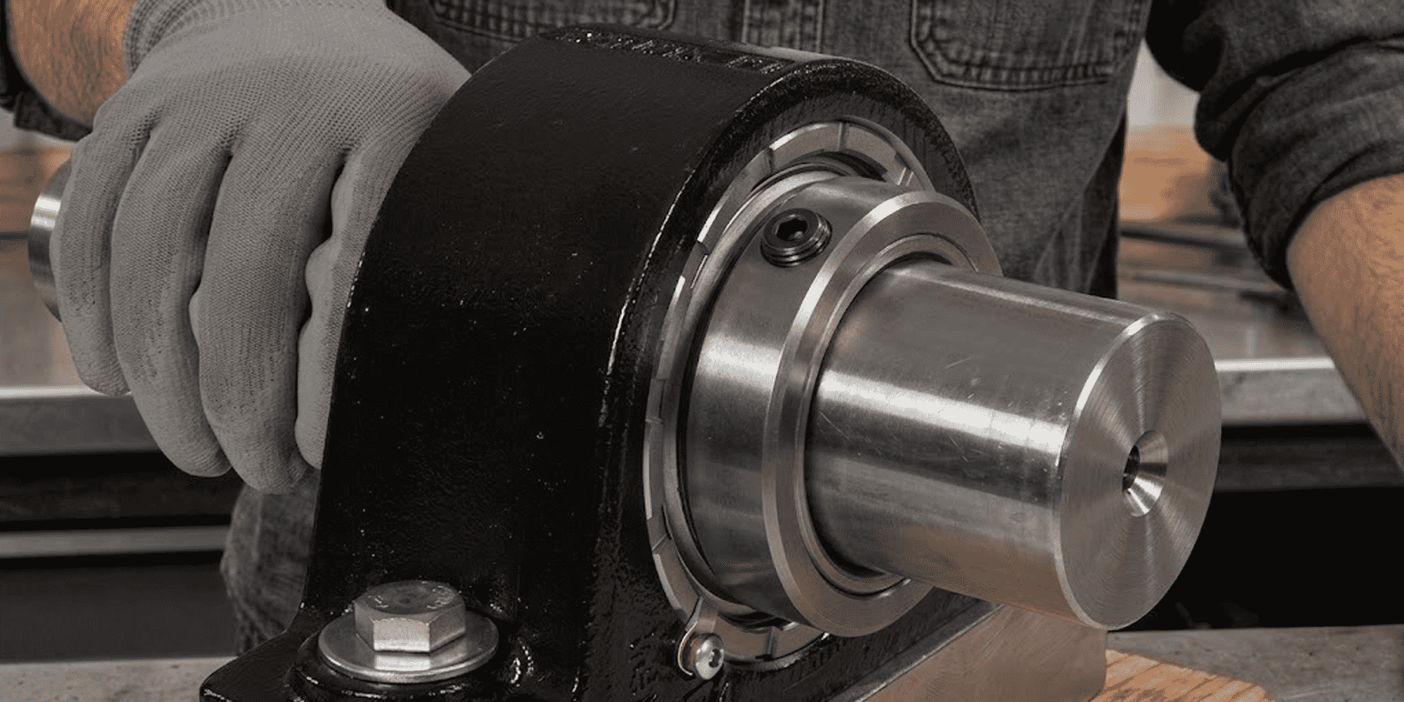
Quick Answer — 8 Steps Clean and inspect the shaft Slide the bearing into position Lightly bolt the housing down Set the final mounting...
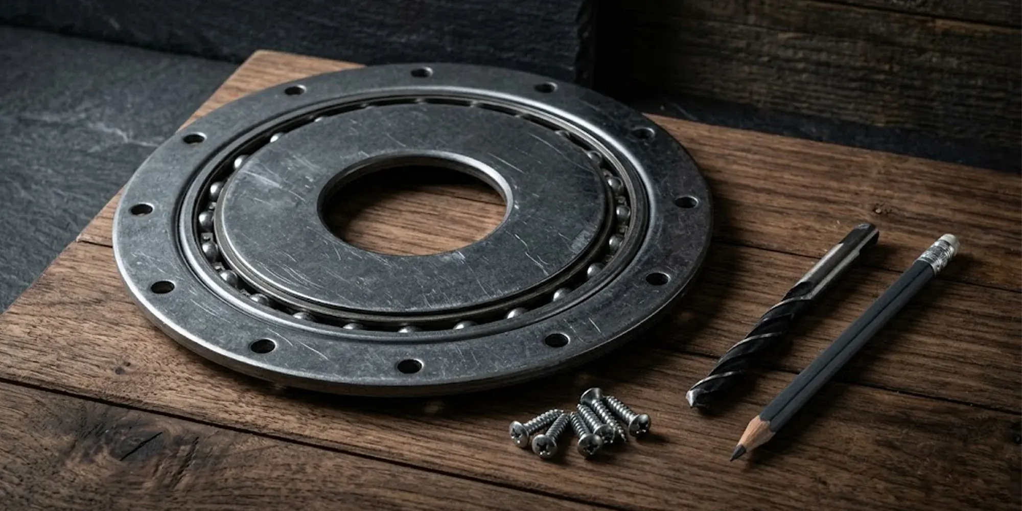
What's Actually in a Lazy Susan Hardware Kit Typical kit contents INCLUDED Turntable bearing Steel plates + ball bearings ⬡ Mounting...