

 Robert
Understanding Bearing Axial Load
Understanding bearing axial load, just like understanding different types of bearing load, is crucial for ensuring the proper functioning and...
Thrust bearings are one of those components that rarely get attention until something goes wrong — a gearbox overheats, a pump shaft walks, a turbine develops abnormal vibration.
At that point, the bearing selection decision from months ago suddenly matters a great deal.
This guide covers what thrust bearings are, how they work, which type fits which load condition, and what to check when selecting one for a real application.
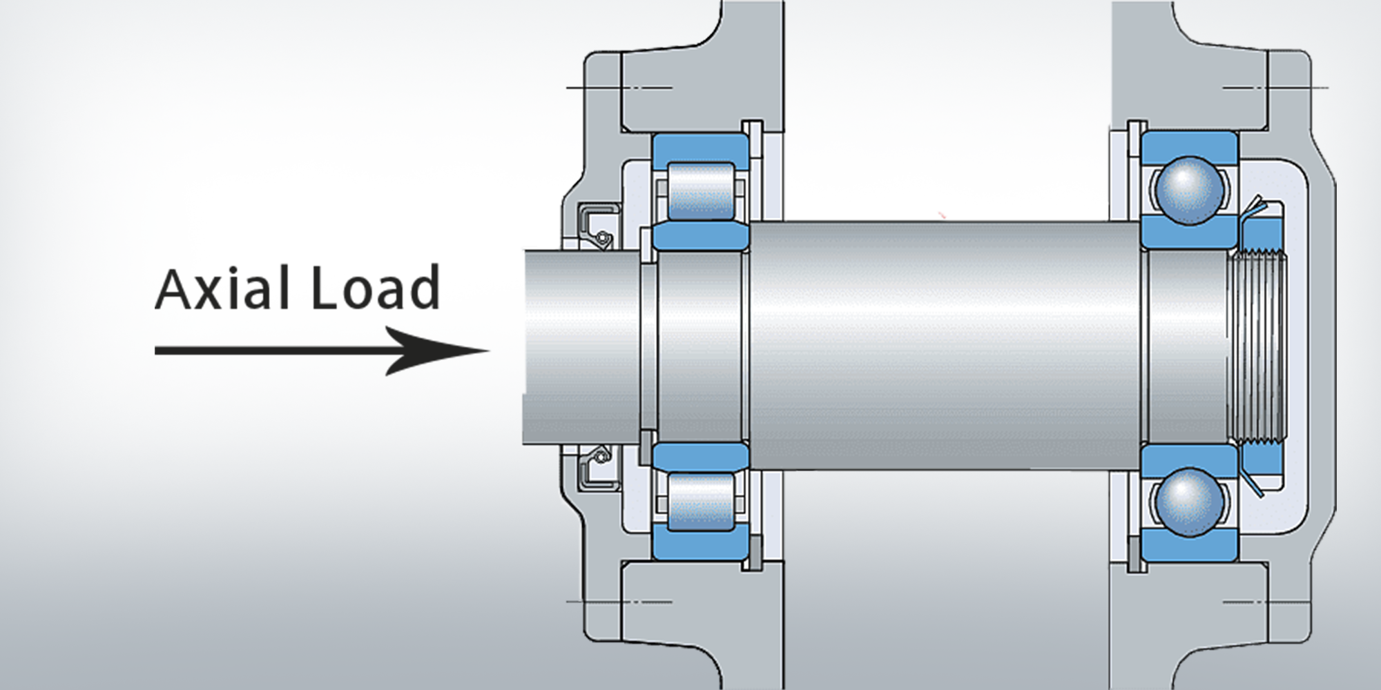
A thrust bearing is a rotary bearing designed to carry axial loads — forces that act along the axis of shaft rotation.
Unlike radial bearings, which resist forces perpendicular to the shaft, thrust bearings keep shafts from moving lengthwise under load.
The practical consequence: without a thrust bearing in a centrifugal pump, the impeller would migrate toward the casing under hydraulic thrust and destroy itself within hours.
In an automotive transmission, thrust bearings prevent gear sets from separating under torque-induced axial forces that can reach several kilonewtons.
The distinction from radial bearings is not just geometric — it is functional. Radial bearings use their raceways to redirect perpendicular forces into the housing.
Thrust bearings use flat or angled raceways to redirect parallel-to-shaft forces.
Most thrust bearing types cannot tolerate significant radial loads, and mixing up the two in a design is a common and expensive mistake.
The core mechanism is rolling contact between raceways.
When a shaft transmits an axial force, that force passes through the rolling elements — balls or rollers — into a stationary housing washer, which transfers it to the machine frame.
Rolling elements reduce friction by converting sliding contact into rolling contact, dropping the coefficient of friction from roughly 0.1–0.3 (sliding) to 0.001–0.005 (rolling).
In a properly loaded thrust bearing, the axial force distributes across all rolling elements simultaneously — unlike radial bearings, where only the elements in the load zone carry significant force.
This uniform distribution is why thrust bearings can achieve high static load ratings relative to their physical size.
Misalignment breaks this distribution: even 0.001 inches of shaft tilt concentrates load on one side of the raceway, sharply reducing fatigue life.
Bearing fatigue life follows the ISO 281 L10 formula: for a ball thrust bearing, L10 = (C/P)³ × 10⁶ revolutions, where C is the dynamic load rating and P is the equivalent dynamic load.
For roller thrust bearings, the exponent changes to 10/3.
A bearing rated at 20 kN dynamic load carrying only 10 kN will, in theory, last eight times longer than one running at full rated load.
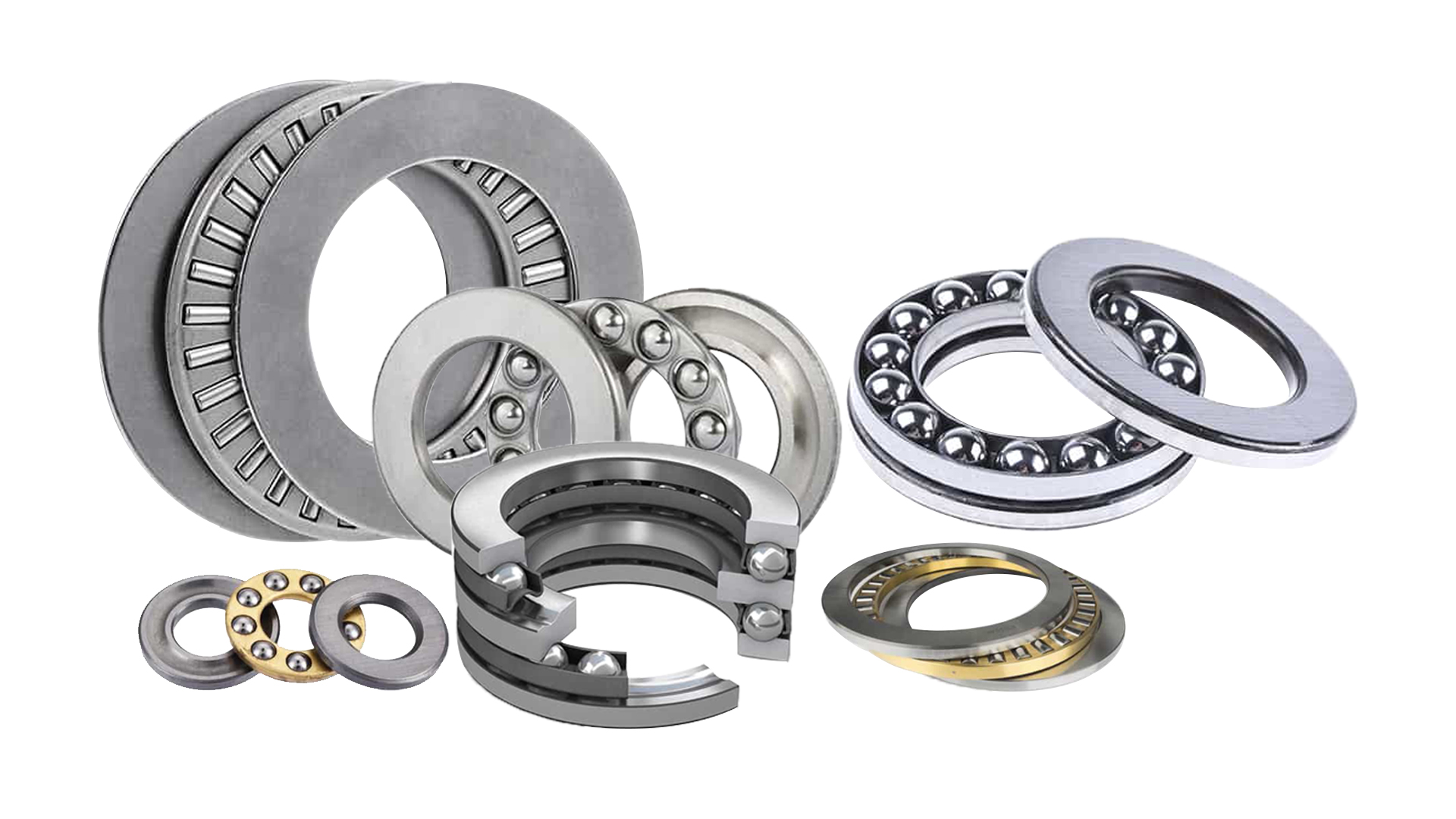
The right type depends on load magnitude, speed, whether radial loads are present, and space constraints.
Here is how the main categories compare, followed by detail on each.
| Type | Axial Load | Radial Load | Max Speed | Typical Application |
|---|---|---|---|---|
| Ball (single-dir.) |
Light–Moderate | None | High | Turntables, valve stems |
| Ball (double-dir.) |
Light–Moderate | None | High | Reversing-load assemblies |
| Angular Contact Ball | Moderate–High | Moderate | Very High | Pumps, compressors |
| Needle Roller | High | None | Moderate | Transmissions, space-limited designs |
| Spherical Roller | Very High | Moderate | Low–Moderate | Extruders, marine propulsion |
| Cylindrical Roller | High | None | Moderate | Gearboxes, turbines |
| Tapered Roller | Very High | High | Low–Moderate | Automotive axles, bevel gearboxes |
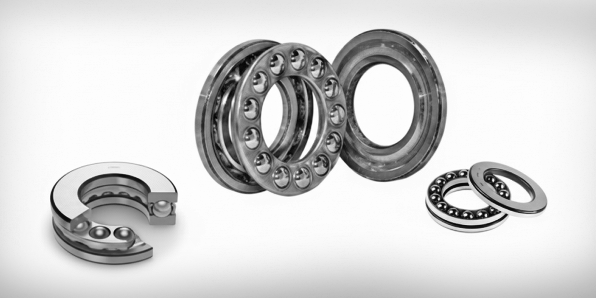
Ball thrust bearings use steel balls running in grooved raceways between two flat washers — a shaft washer that rotates with the shaft and a housing washer that stays stationary.
The design is simple, compact, and effective for light-to-moderate pure axial loads at relatively high speeds.
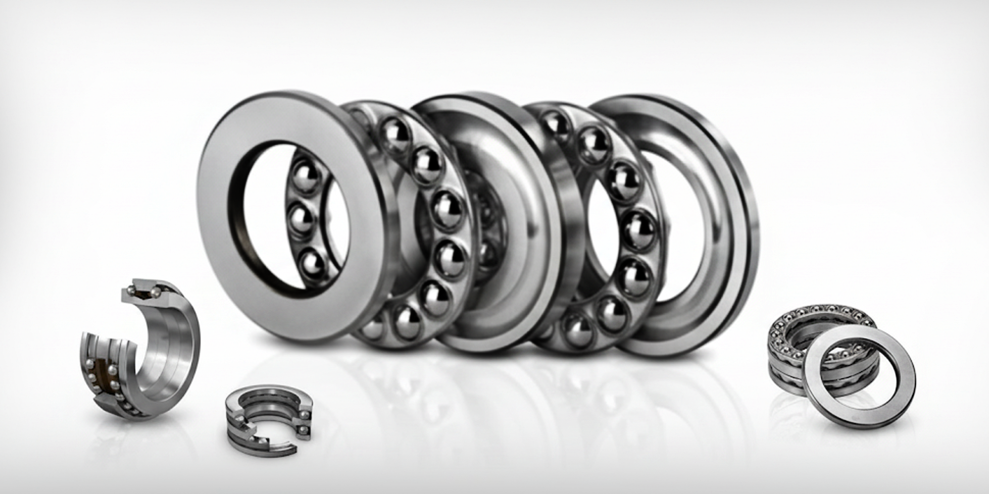
Single-direction thrust ball bearings carry axial load in one direction only and are among the most common thrust bearing configurations.
Double-direction thrust ball bearings add a second row of balls and a central shaft washer, allowing load in both axial directions — useful in applications where thrust reverses, such as reciprocating mechanisms or certain valve actuators.

Miniature ball thrust bearings follow the same principle at bore sizes from 3 mm upward, used in precision instruments, dental handpieces, and optical positioning stages where space is a hard constraint.
Ceramic thrust ball bearings and stainless steel thrust ball bearings address specific environments.
Ceramic (Si₃N₄) elements reduce weight by roughly 40% compared to steel, run cooler under high-speed conditions, and resist corrosion without coatings.
316L stainless is the standard choice for washdown or mildly corrosive environments; 440C stainless offers higher hardness and load capacity where corrosion is less severe.
Angular contact bearings sit at the intersection of radial and thrust bearing design.
Their contact angle — typically 15°, 25°, or 40° — determines how load distributes between the axial and radial directions.
A 40° contact angle gives substantially higher axial capacity than a 15° version of the same bearing size, at the cost of reduced radial load handling.

Common applications include centrifugal pump shafts, screw compressors, and bevel gearbox pinion positions — anywhere the shaft generates both axial and radial force simultaneously.
When bidirectional axial loads are present, these bearings are mounted in pairs in back-to-back (DB) or face-to-face (DF) configurations to handle thrust from both directions while maintaining precise shaft positioning.
Understanding bearing preload is essential when setting up paired angular contact arrangements.
Where ball bearings make point contact with their raceways, rollers make line contact — a longer contact zone that distributes load over a larger area and dramatically increases load capacity.
The trade-off is higher friction at speed and reduced maximum RPM compared to equivalent ball designs.

Needle roller thrust bearings use rollers with a length-to-diameter ratio greater than 3:1, concentrating high load capacity into an extremely thin axial profile.
Automatic transmission clutch packs, for instance, often use stacked needle thrust bearings with an axial cross-section under 5 mm.

Spherical roller thrust bearings use barrel-shaped rollers that allow the bearing to self-align — tolerating shaft deflection and housing misalignment up to approximately 3° without significant life reduction.
This makes them the go-to for heavy, slow-turning applications: large extruder screws, crane hooks, marine propeller shafts, and rolling mill machinery where axial loads can exceed 500 kN.
For a deeper comparison of roller types, see spherical vs. cylindrical roller bearings.

Tapered roller thrust bearings have rollers oriented at an angle to the shaft axis, creating a larger contact area than cylindrical rollers.
They handle combined heavy axial and radial loads — which is why they dominate automotive wheel hubs and differential pinion positions, where cornering loads combine with drive thrust continuously.

Thrust bearings appear wherever rotating shafts generate or resist axial force.
The loads, speeds, and environmental conditions vary enough across industries that almost every thrust bearing type finds a home somewhere.
Selection starts with three numbers: axial load (N or kN), shaft speed (RPM), and required service life (hours or L10 million revolutions).
Everything else — type, size, material, lubrication — follows from those inputs.
Key Selection Parameters
|
1
|
Load Type Pure axial only → ball or cylindrical roller thrust. Combined axial + radial → angular contact or tapered roller. Heavy axial + misalignment → spherical roller thrust. |
|
2
|
Speed — ndm Value ndm = RPM × mean bearing diameter (mm). Ball types: ndm up to ~500,000. Roller types: ~200,000–300,000. Exceeding rated ndm causes thermal runaway. |
|
3
|
Life Requirement (ISO 281 L10) Industrial machines: 20,000–30,000 hr target. Automotive: ~150,000 km equivalent. If P doubles, L10 drops by 8× (ball) or ~10× (roller). Select C accordingly. |
|
4
|
Lubrication Grease: suitable to ~120°C and moderate speeds. Oil required above ~80% of limiting speed or >100°C. Check viscosity ratio κ — running at κ <1 dramatically shortens bearing life. |
|
5
|
Environment Washdown → 316L stainless. High heat (>150°C) → heat-stabilized steel. Vacuum / clean-room → ceramic elements + PFPE grease. |
Most thrust bearing failures trace back to installation errors, not material or design deficiencies.
Misalignment, wrong fit, and contamination during assembly account for a substantial share of premature bearing failures in industrial settings.
|
1
|
Verify shaft and housing fits Shaft washer: light interference or close clearance fit. Housing washer: sits freely. Reversed fits cause raceway stress and premature spalling. |
|
2
|
Clean all mating surfaces Particles larger than 1/3 of the EHD film thickness act as stress concentrators. Use lint-free cloths and approved solvents. Avoid compressed air on open bearings. |
|
3
|
Apply force through the correct ring only Never press on rolling elements or the opposite washer. Use a properly sized sleeve or press plate. Impact hammers are not acceptable installation tools. |
|
4
|
Check alignment after seating Flat-washer types: 0° misalignment tolerance. Spherical roller thrust: up to ~3°. Verify with a dial indicator before closing the assembly. |
|
5
|
Apply initial grease fill correctly Fill 30–50% of the free space in the bearing and housing cavity. Overfilling churns grease, generates heat, and accelerates oxidation — a very common installation mistake. |
Relubrication intervals depend on speed, temperature, and bearing size.
As a rough baseline, halve the relubrication interval for every 15°C increase in operating temperature above 70°C, or for every doubling of shaft speed above half the bearing's limiting speed.
Vibration monitoring catches most developing problems before they become failures.
A thrust bearing in good condition produces a consistent vibration signature at steady speed.
Rising broadband noise above 1 kHz usually indicates lubricant degradation.
Discrete frequency peaks at ball- or roller-pass frequency (BPFO/BPFI) indicate raceway damage — replacing the bearing at this stage costs a fraction of what unplanned downtime costs in most production environments.
The table below covers the most common failure symptoms and their likely causes.
For a broader look at bearing wear patterns across all bearing types, that article goes into further detail.
| Symptom | Likely Cause | Action |
|---|---|---|
| Elevated temperature (>+15°C above baseline) | Overgreasing, wrong lubricant viscosity, overload | Check fill level; verify κ ratio; confirm load against C rating |
| One-sided raceway wear pattern | Shaft misalignment or housing bore out-of-square | Realign shaft; re-machine or replace housing; switch to spherical roller type if misalignment is unavoidable |
| Pitting or flaking on raceway (spalling) | Fatigue from overload or end-of-life | Replace bearing; recalculate L10 with correct load input; consider a higher C rating |
| Corrosion pitting across rolling elements | Water or chemical ingress through seal | Improve sealing; switch to stainless or ceramic elements; use corrosion-inhibiting grease |
| Discrete frequency noise at BPFO/BPFI | Early-stage raceway damage | Plan controlled replacement at next maintenance window; do not run to catastrophic failure |
Standard flat-washer ball and roller thrust bearings carry zero radial load — even small radial forces cause skidding and rapid cage wear. Angular contact and tapered roller designs are the exceptions: they can carry meaningful combined loads because their contact geometry redirects force through both the axial and radial planes simultaneously.
The load direction each is designed to carry. Radial bearings support forces perpendicular to the shaft — the weight of a gear, for instance. Thrust bearings support forces along the shaft axis — the forward push of a propeller or the separation force in a helical gear set. Most rotating shafts need both types: a radial bearing to support shaft weight and a thrust bearing to control axial position.
Three reliable indicators: (1) vibration analysis showing bearing-frequency peaks at BPFO or BPFI, (2) operating temperature rising more than 15°C above the established baseline without a change in load or speed, and (3) visible wear — looseness, roughness during manual rotation, or discoloration on the raceways. Waiting for audible failure noise means the bearing is already destroying itself and possibly the surrounding components.
For pure axial loads, spherical roller thrust bearings reach the highest ratings — some catalog sizes exceed 3,000 kN static capacity. For combined axial and radial loads at moderate speeds, tapered roller bearings offer the best balance. Ball thrust bearings have the lowest load capacity but the highest speed capability, making them the right choice when load is moderate and RPM is high.
Yes, provided the housing has a grease fitting and purge port. Inject new grease slowly — with the machine running if safe to do so — and ensure old grease has somewhere to exit. Forcing in more grease without relieving the old grease simply increases churning heat and accelerates degradation.
Thrust bearings do one job — manage axial load — but they do it across an enormous range of scales, from a 3 mm miniature ball bearing in a precision instrument to a spherical roller unit handling over 3,000 kN in a steel mill. Choosing the right type, sizing it to the L10 target, installing it without introducing misalignment or contamination, and monitoring it in service covers the vast majority of what determines whether a thrust bearing reaches its design life or fails early.
For application-specific selection help or to review load ratings for a particular series, contact the LILY Bearing technical team directly.
Understanding bearing axial load, just like understanding different types of bearing load, is crucial for ensuring the proper functioning and...
As a main bearing supplier, Lily Bearing is well-known for its high-quality bearings, professionalism as well as top-torch services. Undoubtedly, ...
When you turn on the tap, have you ever wondered how the tap water you use every day reaches the water pipes in your home? Actually, this should be...