

 William
How Do Gears Work? A Guide to Speed, Torque, and Gear Ratios
Why do some mechanical systems prioritize raw power while others focus on high-speed rotation? At LILY Bearing, I’ve seen how a tiny adjustment in...
Worm gears are everywhere in daily life. You'll find them in car steering systems, conveyor belts, and stand mixers—often working invisibly behind the scenes.
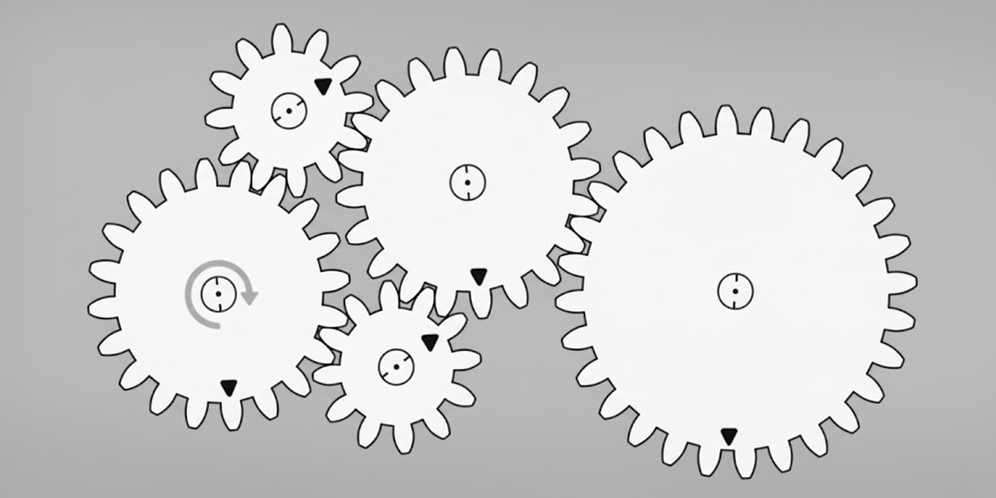
These compact gears trade speed for power, delivering smooth, controlled motion with high reduction ratios. If you're new to gear mechanics, see how gears work before diving in.
They represent one of the key technologies in our comprehensive line of gear products. If you're comparing options, our complete guide to types of gears covers the full range.
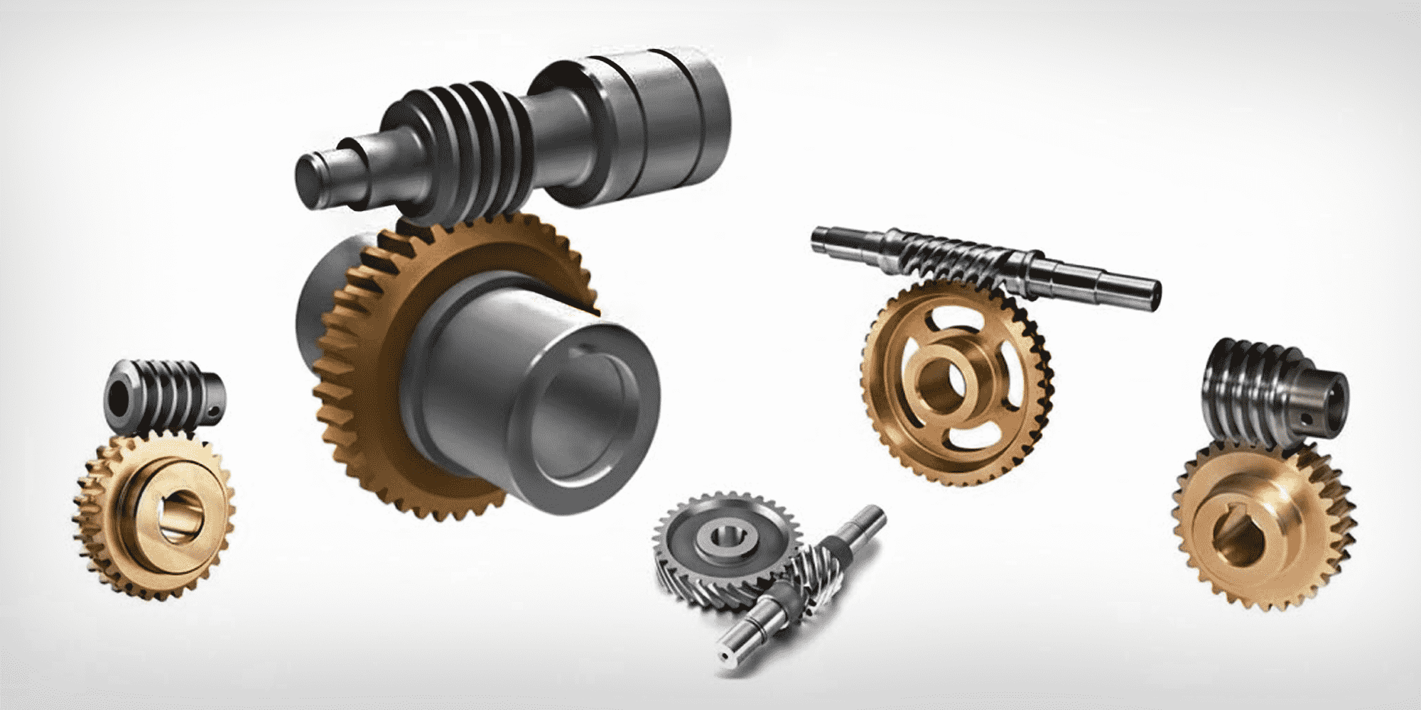
At its core, a worm gear system consists of two main components: the worm (which resembles a screw) and the worm wheel.
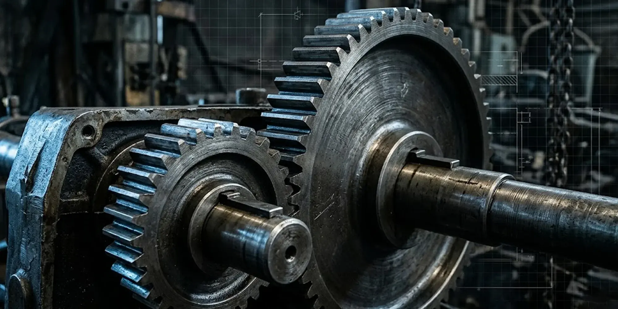
As the worm shaft rotates, its worm thread gradually pushes against and meshes with a worm wheel, causing it to turn.
Unlike helical gears, worm gears use sliding action rather than rolling contact.
This arrangement creates what engineers call a "self-locking" feature.
In most cases, force applied to the worm wheel cannot drive the worm in reverse.
This unique sliding contact creates smooth, quiet operation.
However, it also generates more heat and isn't suitable for high speed applications.

The worm essentially functions as the driver in the system. Typically made from hardened steel, it features one or more helical threads.
A single thread (or start) worm will produce a much higher ratio speed reduction than a multi-start design.
The thread spirals at a specific angle called the lead angle. This angle affects the gear's efficiency and self-locking capability.
The worm wheel, usually constructed from softer materials like bronze, meshes with the worm.
The number of teeth on the worm wheel is a key factor in determining the final gear ratio.
This material combination allows the system to better absorb shock loads and reduces the risk of catastrophic failure. For a deeper look at materials and processes, see how gears are made.

Understanding the different types of worm gears is key to selecting the right one for your application.
Different geometries and engagement styles create different worm gear types.
Each type has distinct load limits, costs, and use cases.
This is the simplest type of worm gear. The worm is a straight cylindrical worm, and the worm wheel has straight teeth, resulting in minimal point contact.

This is the most common type found in industry. The wheel has a concave throat that wraps around the cylindrical worm. This creates a larger line contact area.

This design offers the highest performance. It uses double-throated geometry.
The worm has an hourglass profile, and the wheel throat wraps around it on both sides.
This creates the largest possible contact area.

The gear ratio in a worm drive is calculated using a straightforward formula:
Gear Ratio (i) = Z₂ / Z₁
Example:
A single-start worm (Z₁=1) driving a 60-tooth wheel (Z₂=60) yields a 60:1 ratio.
This means the input shaft must rotate 60 times for every single rotation of the output shaft. As a result, this achieves massive speed reduction and proportional torque increase—all in just one stage.
This single-stage efficiency is a key advantage.
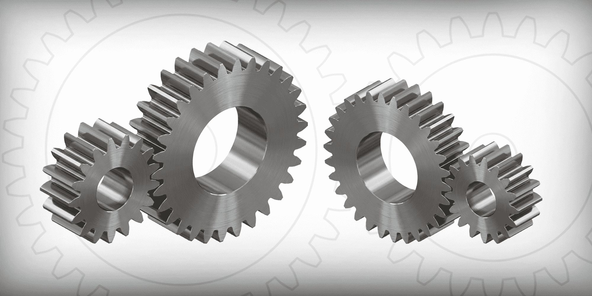
In contrast, achieving 60:1 with spur gears is possible, but it requires multiple stages. Each additional stage adds size and weight. The result is a much bulkier system.
For this reason, worm gears are the superior choice when you need high-ratio reduction in a compact space.

The unique design of worm gears provides several compelling benefits:
Despite their strengths, worm gears aren't perfect for every situation:
Worm gears are the best choice when you need compact size, high reduction ratio, self-locking safety, and quiet operation.
The irreversible self-locking feature is paramount here, providing inherent safety.
These applications benefit from the unit's role as a robust speed reducer, which allows it to achieve large speed reductions and amplify torque in a single stage.
The high reduction ratio enables fine control and stable positioning.

The geometry is ideal for transmitting power at 90 degrees in a minimal space.
Material selection is a critical balance between strength, wear resistance, and cost.
The standard practice pairs a hard worm with a softer worm wheel, creating a sacrificial component that protects the more critical worm from damage.
Due to the predominant sliding motion between the worm and wheel, effective lubrication is not just beneficial—it is critical for performance and longevity.
The high sliding friction generates substantial heat and poses a constant risk of wear.

This unique action necessitates specialized lubricants, typically of high viscosity and often containing extreme pressure (EP) additives. As noted in the ASME Press guide on worm gear lubrication, the sliding action in worm gears makes effective oil film formation more complex than in other gear types.
These dedicated oils or greases form a robust film to separate the metal surfaces but can be difficult to filter and often require a dedicated lubrication system on-site.
Proper lubrication serves three key functions:
Selecting a worm gear set involves evaluating your application against these key criteria:
Consult an application engineer for demanding projects to finalize your selection.
Worm gears occupy a unique position in the world of power transmission. Their ability to provide high ratio reduction in compact spaces, combined with self-locking capability, makes them indispensable.
Worm gears are not the most efficient gear type. However, they excel in specific situations. Choose them when safety, compactness, and controlled motion are your top priorities.
As a leading gear supplier, we offer worm gears and many other gear types. These include helical gears, spur gears, bevel gears, and more. You may also want to explore the leading gear manufacturers to understand who's behind the industry. We can help you find the right solution for your project.
Almost never. Their self-locking design prevents reverse operation, making them essential for elevators and hoists where safety is critical.
Simple: divide the worm wheel teeth (Z₂) by the worm starts (Z₁). A single-start worm with a 60-tooth wheel gives you 60:1—the input spins 60 times for every one output rotation.
More than you'd think. Guitar tuning pegs, car window regulators, stand mixers, elevator drives, conveyor belts, gate openers—if a device moves slowly, quietly, and stays put when power is off, there's likely a worm gear inside.
Choose worm gears for high reduction ratios, self-locking safety, and compact right-angle drives. Choose helical gears when efficiency, high speed, and reversible motion are the priority. For a detailed breakdown, read our helical vs. spur gears comparison.
Frequently, yes. Lower efficiency means heat buildup—continuous duty applications often need cooling fins or a fan to stay within safe operating temperatures.
Lubrication is the deciding factor. Keep the EP oil fresh and the load within spec, and a good set can run for tens of thousands of hours. Most failures come down to one thing: neglected lubrication.
Why do some mechanical systems prioritize raw power while others focus on high-speed rotation? At LILY Bearing, I’ve seen how a tiny adjustment in...
Walk into any factory, open up a household appliance, or look inside a medical device, and you'll almost certainly find a spur gear doing quiet,...
Quick answer: Gear ratio = driven gear teeth ÷ drive gear teeth. A 60-tooth driven gear meshed with a 20-tooth drive gear gives a 3:1 ratio — one...