

 Robert
Idler Pulley vs Drive Pulley: What's the Difference?
Open any belt-driven machine—an automotive engine, an industrial conveyor, a CNC router—and you'll find at least one pulley that spins without being...
A pulley is one of the six classical simple machines—but that simplicity is deceptive.
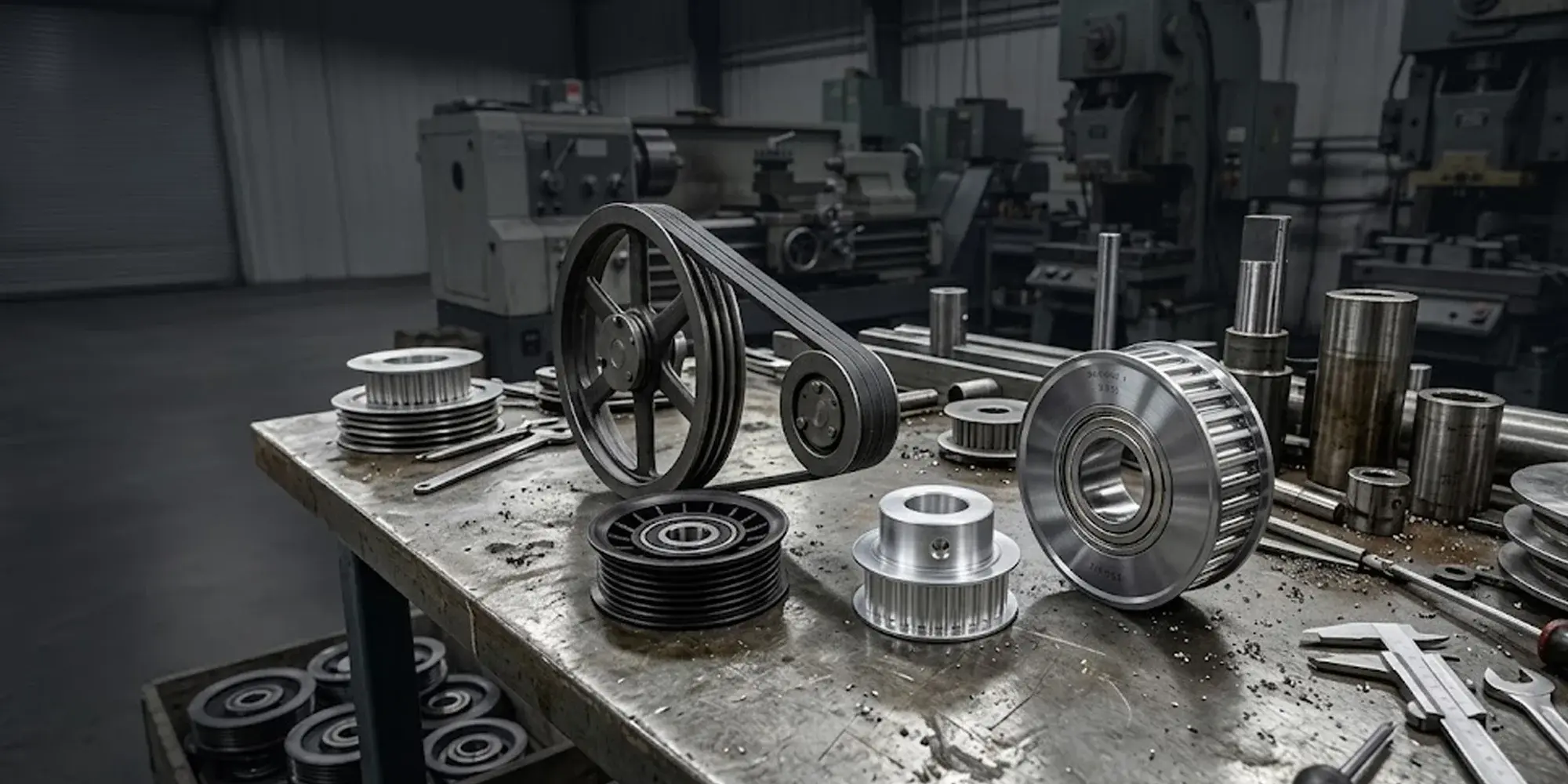
In modern industrial and mechanical applications, pulleys span dozens of configurations, each optimized for a specific function: transmitting torque, redirecting force, maintaining belt tension, or lifting loads.
Choosing the wrong type costs more than just efficiency; it causes premature wear, misalignment, and system failure.
This guide breaks down the main types of pulleys—belt, idler, rope, and timing—and explains exactly where and why each one is used.
Most pulley classification systems use one of three criteria: function (what role the pulley plays in the system), drive type (the medium connecting the pulley—belt, rope, or chain), or design configuration (single groove, double, quick-disconnect, etc.).
In practice, these overlap. A timing belt pulley is classified by drive type (synchronous belt) and tooth profile (trapezoidal or curvilinear).
Understanding all three layers helps you spec the right component on the first attempt.
Belt pulleys transmit rotational power between shafts using a continuous belt—no direct shaft-to-shaft contact.
They are the workhorse of industrial drive systems: HVAC units, agricultural machinery, machine tools, and automotive accessories all rely on belt pulleys.
The V-belt pulley—also called a sheave—has a trapezoidal groove that mates with the wedge profile of a V-belt.
The wedging action amplifies friction, allowing high torque transmission without belt slippage.
Standard groove angles range from 34° to 40°, with tighter angles used for high-speed, low-torque applications.
.webp?width=357&height=357&name=V-Belt%20Pulleys%20(Sheaves).webp)
V-belt systems can transmit power over center distances up to 5 m and are tolerant of minor shaft misalignment (typically ±0.5°).
They are not suitable for precise speed ratios because belt slip of 1–3% is inherent to the design.
Flat belt pulleys have a smooth, crowned face—the slight crown (typically 1:100 taper) keeps the belt centered under load.
They run quieter than V-belt systems and are preferred where high-speed operation (up to 50 m/s belt speed) or crossed-belt configurations are required.

The trade-off is lower power density per unit width compared to V-belt designs, requiring wider pulleys for equivalent torque transmission.
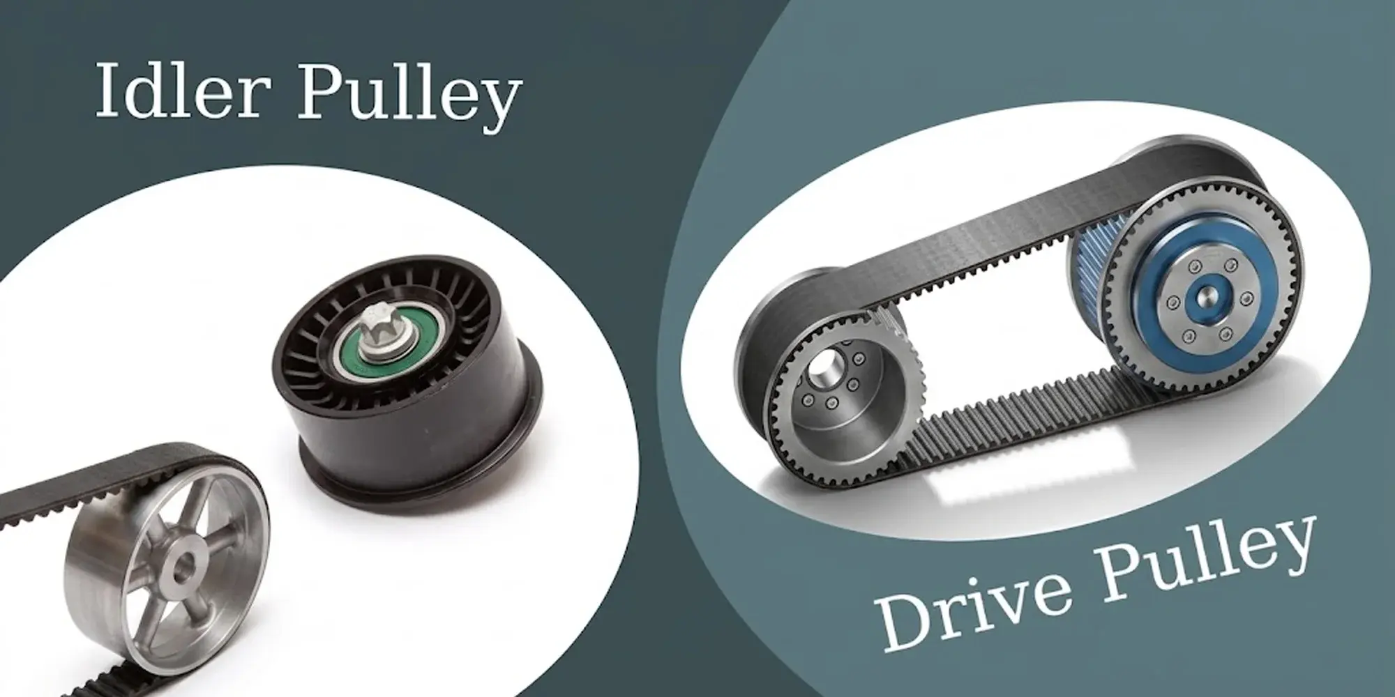
An idler pulley does not transmit power—it guides, supports, or tensions a belt or chain without connecting to a drive shaft.
Every automotive engine has at least one; modern serpentine systems often use three or more.
For a detailed breakdown of how idler and drive pulleys differ in design, failure modes, and field identification, see our idler pulley vs drive pulley comparison.

Idler pulleys serve two distinct purposes depending on placement: tensioner idlers maintain minimum belt tension on the slack side, while guide idlers redirect the belt path or increase wrap angle on the drive pulley.
Increasing wrap angle from 120° to 180° can raise torque capacity by 30–40%, depending on the friction coefficient.
Most idler pulleys run on sealed ball bearings, and bearing failure—not groove wear—is the dominant failure mode.
A squealing or grinding noise from an idler almost always means the bearing is failing.
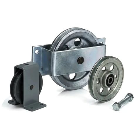
In lifting and rigging applications, the sheave is the grooved wheel; the pulley is the complete assembly including the frame (block) and fastening hardware.
The groove profile must closely match the rope or cable diameter—a groove that's too wide allows the rope to twist and wear unevenly, while too narrow a groove pinches and accelerates fatigue cracking in the wire strands.
A single fixed pulley only changes the direction of the applied force—the mechanical advantage (MA) is 1:1.
A single movable pulley provides an MA of 2:1, meaning a 500 kg load requires only 250 kg of pull force (ignoring friction).
In practice, friction losses in sheave bearings reduce effective MA by 3–5% per sheave, which is why rigging engineers always calculate friction factors into load calculations for critical lifts.
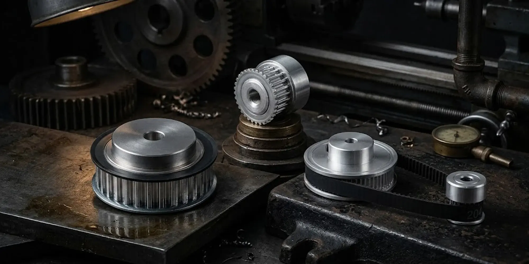
Timing belt pulleys are toothed pulleys designed to mesh with the teeth of a synchronous (timing) belt.
Unlike V-belt or flat belt systems, there is no slip—the tooth engagement creates a positive mechanical lock between belt and pulley, maintaining an exact speed ratio between input and output shafts.

This makes timing pulleys the only viable choice for applications where position accuracy or speed synchronization is non-negotiable: CNC machine axes, 3D printer extruders, robotic arms, and automotive valve timing systems all depend on timing belt drives.
For full specification guidance—pitch selection, tooth count, bore configuration, and material—see our timing belt pulley guide.
Tooth profile matters as much as pitch.
Trapezoidal teeth concentrate stress at the tooth root, limiting fatigue life at high loads.
Curvilinear tooth profiles—such as GT2 and HTD—distribute stress more evenly, increasing torque capacity by 20–30% for the same pitch and pulley diameter.
L, XL, H, and MXL series in aluminum, steel, and corrosion-resistant configurations. 497 products in stock.
View Timing Belt Pulleys →A sheave is the grooved wheel itself. A pulley is the complete assembly—sheave, axle, bearing, and housing (block). In belt-drive contexts, the terms are used interchangeably. In rigging and lifting, the distinction matters for component replacement and load rating purposes.
No. V-belt pulleys have smooth or trapezoidal groove profiles designed for friction drive. Timing belts require toothed pulleys with matching pitch and tooth geometry. Running a timing belt on a V-belt sheave will strip the belt teeth within a short period of operation.
A general rule is no fewer than 10–12 teeth in mesh with the belt at any time to distribute load evenly. For high-torque applications, 18–24 teeth on the smaller pulley is a common starting point. Fewer teeth increase per-tooth stress and accelerate belt fatigue.
Bearing failure accounts for the majority of idler pulley failures. Contamination (dirt, moisture), inadequate lubrication, and excessive belt tension are the three leading causes. Most OEMs recommend replacing idler pulleys every 60,000–100,000 km in automotive applications, regardless of apparent condition.
Aluminum is the default choice—it machines precisely, resists corrosion adequately in most environments, and has a favorable strength-to-weight ratio. Steel pulleys are specified for high-load, high-cycle applications. For food processing, pharmaceutical, or marine environments, anodized aluminum or 316 stainless steel with sealed bearings is the appropriate specification.
Open any belt-driven machine—an automotive engine, an industrial conveyor, a CNC router—and you'll find at least one pulley that spins without being...
In any drive system where the output shaft must rotate at a precise, predictable ratio to the input shaft—think CNC machine axes, robotic joints,...
A pillow block bearing is a pre-assembled unit that mounts a bearing insert into a housing, ready to bolt directly onto a machine frame. Unlike...