

 Richard
Bad Cam Follower Symptoms: 5 Warning Signs You Shouldn't Ignore
Understanding Bad Cam Follower Symptoms The engine, often referred to as the heart of a vehicle, depends on several components to run smoothly. ...
In most shaft-and-housing assemblies, retaining a plain bushing axially requires either a shoulder machined into the housing or a separate thrust washer — both add cost and length.
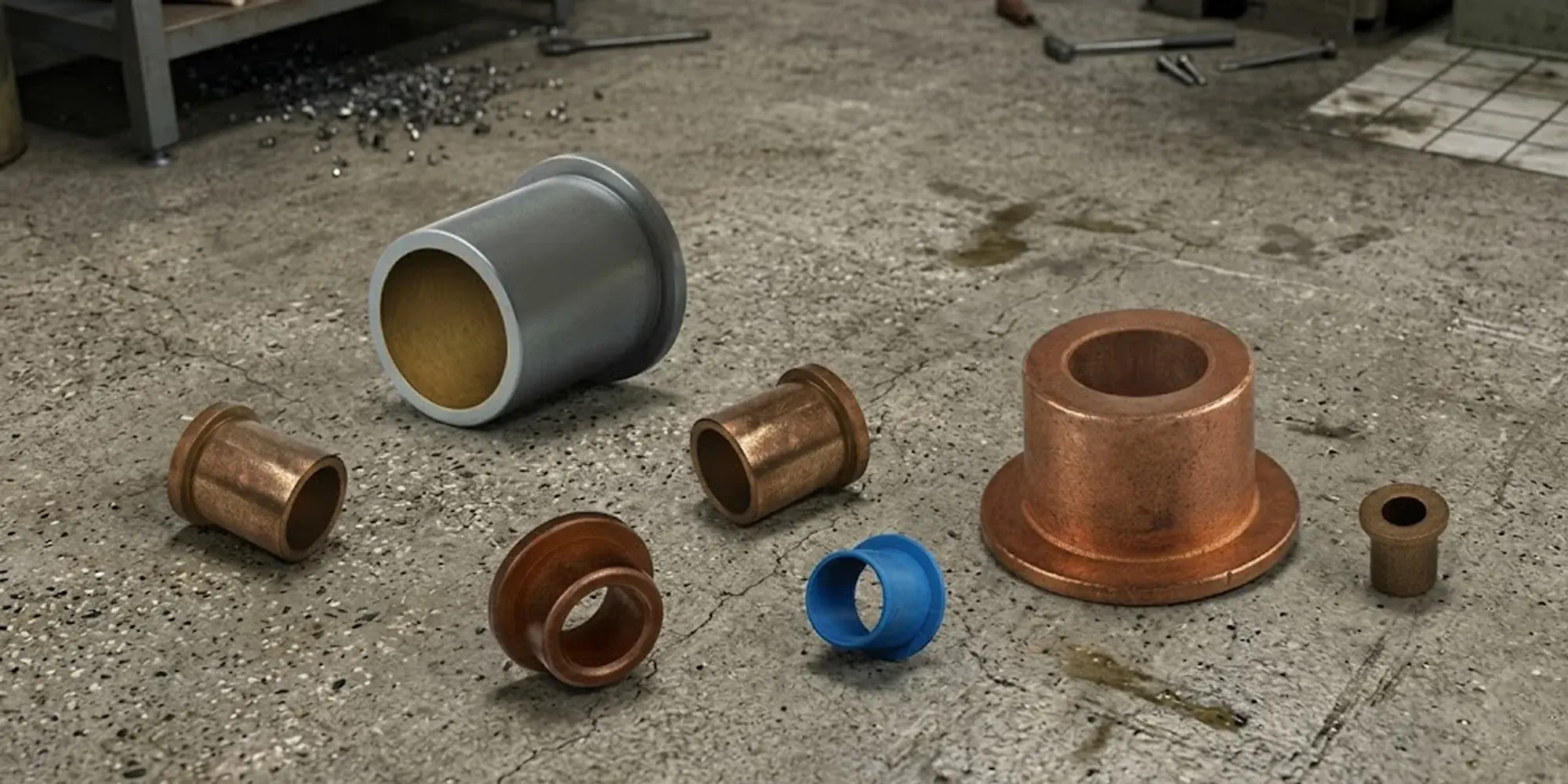
A flanged sleeve bearing solves this in one part: it's a cylindrical bush with a radially extending collar (the flange) at one end.
The flange seats against the housing face and handles axial (thrust) load from the shaft shoulder, while the bore handles radial load. You get both functions without the added components.

That sounds simple, and it is — which is part of why flanged sleeve bearings remain one of the most widely specified plain bearing configurations across industrial machinery, agricultural equipment, automotive linkages, and consumer appliances.
When the load is moderate, the environment is dirty, or the motion is oscillating rather than continuous rotation, a well-chosen flanged bushing will outlast a rolling-element bearing at a fraction of the cost.
Terminology note: "Flanged bush," "flanged bushing," "F-type plain bearing," and "flanged bronze bearing" all refer to the same component. ISO 4379 uses "flanged plain bearing" as the formal designation.
The flanged sleeve family divides primarily by manufacturing method, which determines wall thickness, dimensional precision, load capacity, and lubrication requirements.
Getting this classification right is the first decision in any selection process.
Cut from solid bar stock — typically bearing bronze, aluminum bronze, or cast iron — these offer the highest dimensional accuracy and the best load-to-size ratio.
Wall thickness commonly runs 2–20 mm depending on bore diameter.
They're the default choice for continuous rotation above 3 m/s surface speed or where radial pressure exceeds 15 MPa.
The tradeoff is cost: machining cycle times make them 3–5× more expensive per unit than sintered equivalents at the same bore size.
Formed from compressed and sintered metal powder — most commonly Cu-Sn10 bronze or iron — with interconnected pores occupying 18–25% of total volume.
Those pores hold oil by capillary action and release it to the shaft surface as the bearing heats up in service.
The result is a genuinely maintenance-free bearing for light-to-moderate duty, with bore sizes from 3 mm to 50 mm covered by most standard catalogs.
Dynamic load capacity is limited to roughly 7 MPa; above that, the pore structure compresses and the self-lubrication mechanism degrades.
See LILY Bearing's oil-embedded flanged sleeve bearing range for standard metric and inch series.
%20Flanged%20Bushings.webp?width=460&height=460&name=Sintered%20(Oil-Embedded)%20Flanged%20Bushings.webp)
Rolled from strip metal into cylindrical form, then flanged.
The most common construction is steel-backed with a sintered bronze intermediate layer (~0.25 mm) and a PTFE/polymer sliding layer (~0.025 mm).
Overall wall thickness is typically 1.0–2.5 mm, making these the go-to choice where housing bore space is constrained.
They handle a wide temperature range (−200°C to +280°C for PTFE overlay) and run dry without external lubrication.
Common in automotive door hinges, agricultural linkages, and hydraulic cylinder gudgeon pins.
%20Flanged%20Bushings.webp?width=460&height=460&name=Wrapped%20(Thin-Wall)%20Flanged%20Bushings.webp)
Steel or bronze shell with a babbitt, aluminum-tin, or lead-bronze lining cast or rolled onto the bore surface.
The steel back provides structural rigidity; the soft lining (typically 0.1–0.5 mm thick in precision applications, up to 1.0 mm in heavy-duty designs) absorbs hard debris particles and conforms to minor shaft misalignment.
Bi-metal bushings appear most often in engine connecting rods, transmission shafts, and large agricultural gearboxes.

Moulded or machined from PTFE composites, PEEK, nylon (PA66), or acetal (POM).
Maximum continuous load is relatively modest — typically under 10 MPa — but their chemical inertness and zero metallic contamination make them the only practical option in food processing equipment, pharmaceutical machinery, and semiconductor handling systems.
LILY Bearing's dry-running flanged series covers the most common polymer configurations. For marine and chemical-process environments, the corrosion-resistant flanged range adds stainless and composite options.
%20Flanged%20Bushings.webp?width=491&height=491&name=Polymer%20(Self-Lubricating)%20Flanged%20Bushings.webp)
Wrong material choice is the most common root cause of premature bearing failure — not incorrect load calculation, not bad installation.
Pick the wrong alloy for the temperature or lubrication condition and it fails regardless of how well everything else was done.
The cards below summarize the four main families and where each one actually belongs.
RoHS note: SAE 660 and SAE 841 contain lead (Pb). Under EU RoHS Directive 2011/65/EU and its 2015 amendment, leaded copper alloys in certain product categories require exemption documentation. Verify compliance requirements before specifying them for new EU-market designs. Lead-free alternatives (C93700, PTFE composites) are available from most distributors.
Flanged sleeve bearing dimensions are standardized under ISO 4379:2021 (metric) and corresponding ANSI/ABMA inch series.
Five parameters define the bearing: bore diameter (d), outer diameter (D), total length (L), flange outer diameter (D₁), and flange thickness (t).
The table below lists representative sizes from the ISO metric series.
Tolerance system: ISO 4379 specifies H7 bore tolerance for machined types and H8 for sintered types. Housing bore is typically js6 for transition fits or p6 for press fits. After pressing a sintered bushing into an H7 steel housing, the bore typically closes by 0.5–2% of wall thickness — always finish-ream to final bore size after installation.
The standard design parameter for plain bearings is the PV value — the product of bearing pressure P (MPa) and surface velocity V (m/s).
PV is a proxy for frictional heat generation rate.
Exceed the material's PV limit and the bearing surface overheats, the lubricant film collapses, and seizure follows.
The limits below are for continuous running at rated temperature; intermittent or oscillating duty typically permits 2–3× higher P values because heat dissipates between cycles.
Important: PV limits vary between manufacturers and compound formulations. The values above are representative engineering ranges; always validate against the specific product datasheet before finalising a design. SAE 660 bronze can reach 3.5–5.0 MPa·m/s under a stable hydrodynamic oil film (per bearing manufacturer technical data from GGB and Igus), but will drop sharply if oil supply is interrupted.
Knowing how to choose a flanged sleeve bearing for your application comes down to working through seven parameters in order.
Skip one and you risk either over-specifying (wasting money) or under-specifying (premature failure). Here's the sequence:
LILY Bearing's flanged sleeve range covers oil-embedded, dry-running, corrosion-resistant, and multipurpose configurations in metric and inch series. Need help selecting the right type?
Browse Flanged Sleeve BearingsThe majority of premature flanged bearing failures trace back to incorrect fit or improper installation — not to material underperformance.
Get the press-fit and the bore finish right and the bearing will perform to spec. Get them wrong and it will fail within days regardless of material grade.
Lubrication regime determines bearing life more than material selection in many applications.
There are three regimes, and they require different bearing types.
Choosing the wrong regime — specifying a hydrodynamic bearing where only boundary lubrication is achievable, for instance — is a common and avoidable design error.
The shaft generates a pressurised oil wedge that completely separates it from the bearing bore.
Friction coefficients drop to 0.001–0.01 and wear approaches zero.
This regime requires a continuous oil supply, sufficient shaft speed (determined by the Sommerfeld number for your specific bearing geometry and oil viscosity — not a single universal value), and shaft surface roughness below Ra 0.8 µm.
Most large industrial gearboxes, turbine guide bearings, and high-speed spindles operate here.
SAE 660 bronze and aluminium bronze are the standard material choices.
The oil film is incomplete — shaft and bore asperities make intermittent contact. Friction coefficients typically run 0.05–0.15.
This is the operational reality for most start-stop, oscillating, and low-speed flanged bearing applications, regardless of how much oil is supplied.
Bearing material properties (hardness, embeddability, conformability) dominate wear rate in this regime.
SAE 660 bronze with oil film maintains reliable service at P up to 20 MPa; sintered bronze is more limited at roughly 7 MPa dynamic.
PTFE-overlay and sintered bronze bearings are designed for oil-free operation.
PTFE transfers a molecular film to the shaft surface during initial break-in — the first few hours of service see slightly elevated wear before the transfer film stabilises.
During break-in, keep loads at or below 50% of the rated dynamic value.
For sintered bronze in continuous dry service, maintain PV below 0.12 MPa·m/s; for PTFE overlay, keep below 0.10 MPa·m/s continuous.
LILY Bearing's multipurpose flanged series includes both oil-embedded and dry-running options within the same dimensional family.
Grease re-lubrication intervals for solid bronze bushings: A commonly used starting point in industrial practice is one grease cycle per 250–500 operating hours at moderate duty (P < 10 MPa, V < 1 m/s, T < 60°C). Halve this interval for temperatures above 80°C or high-vibration environments. Use a lithium-complex or calcium-sulfonate grease rated for the operating temperature; avoid greases with EP additives containing active sulfur compounds against bronze, as they can corrode the bearing surface.
A plain sleeve bearing (straight bush) handles radial load only and requires a separate mechanism — housing shoulder, snap ring, or thrust washer — to prevent axial movement.
A flanged sleeve bearing adds the flange collar at one end, which bears against the housing face and handles limited axial (thrust) load in one direction.
The flanged design simplifies assembly, reduces part count, and is the default choice where both radial and moderate thrust loads need to be managed in a compact envelope.
A standard single-flange bushing takes thrust from one direction only — the flange face bears against the housing shoulder.
For bidirectional thrust, use a double-flanged bushing (flanges at both ends) or install two single-flanged bushings back-to-back with flanges facing outward.
The double-flanged configuration adds axial length but eliminates the need for any additional axial retention hardware.
The clearest indicator is diametral clearance: measure shaft diameter and bore diameter with a bore gauge.
When the difference exceeds 0.5–1.0% of the nominal bore diameter (e.g., more than 0.10–0.20 mm on a 20 mm bore), the bearing is approaching end of life.
Supporting signs include rising housing temperature, audible squeaking or knocking at startup, and metallic particles or discolouration in the lubricant.
For critical machinery, periodic vibration analysis can detect sub-synchronous frequencies indicating bearing looseness before visible wear becomes measurable.
For SAE 660 bronze, the shaft should be a minimum of 35 HRC (approximately 325 HB), and ideally 45–60 HRC for continuous rotation or high loads.
Softer shafts wear faster than the bushing, which inverts the intended wear hierarchy — the bearing is meant to be the sacrificial element, not the shaft.
Ground and polished shaft surfaces at Ra 0.4–0.8 µm minimise abrasive wear initiation; avoid turned surfaces left at Ra > 1.6 µm in contact with plain bearings.
Not directly. Even when bore sizes are nominally equivalent (e.g., 1/2" bore ≈ 12.7 mm), outer diameter, length, flange OD, and flange thickness all follow separate dimensional series.
Many manufacturers produce "inch-equivalent" bushings to metric DIN tolerances, which adds another layer of potential mismatch.
Always verify all five key dimensions — d, D, L, D₁, and t — rather than assuming a nominal bore match implies full interchangeability.
FDA-compliant polymer types — PTFE composites, PEEK, or NSF-rated acetal (POM) — are the standard choice.
They produce no metallic contamination, resist washdown chemicals, and run dry without lubrication that could contact food products.
For higher loads in food machinery, glass-fibre-reinforced PTFE composites extend the usable pressure range to ~25 MPa while maintaining compliance.
Stainless steel housings paired with polymer bushings are the most common combination in direct food-contact zones.
Understanding Bad Cam Follower Symptoms The engine, often referred to as the heart of a vehicle, depends on several components to run smoothly. ...
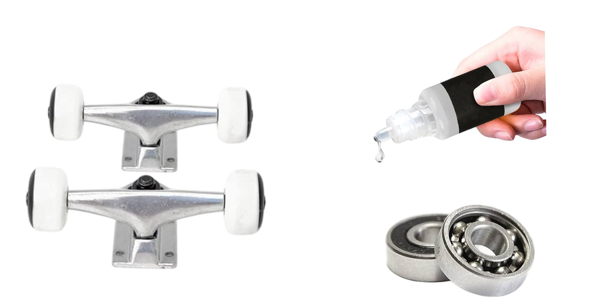
Grease skateboard bearings is crucial for maintaining smooth performance and prolonging the life of the bearings. Every skateboard uses eight...
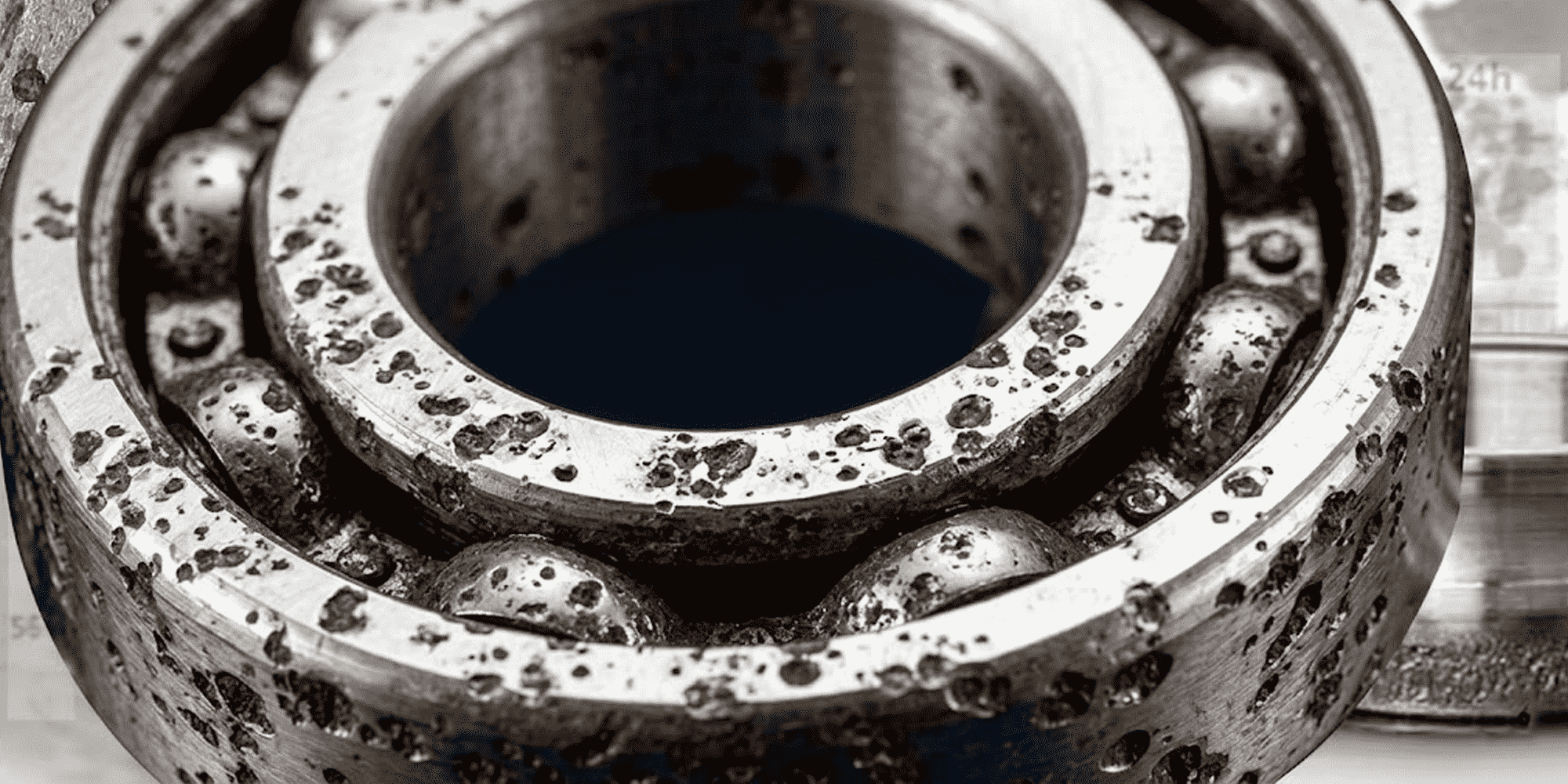
Stainless steel has a strong reputation for being corrosion resistant. So it can come as a real surprise when stainless steel bearings start failing...