

 William
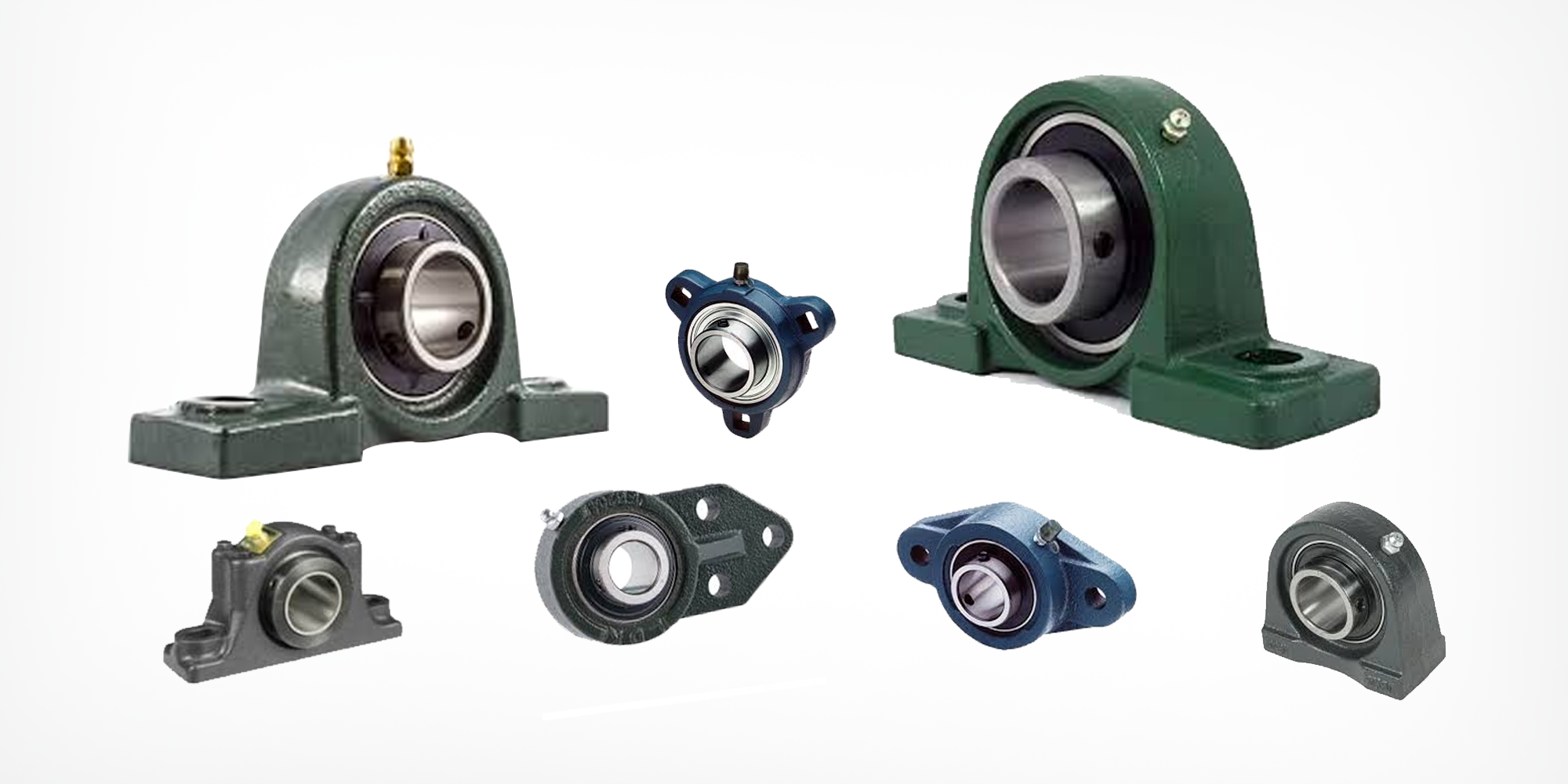
Mounted Bearings: Types, Advantages, and Uses
In the world of machinery, mounted bearings play a pivotal role. They are integral to the smooth operation of various equipment across industries. ...
Choosing the right mounted flange bearing is more than just matching a shaft diameter. It protects your entire power transmission system from premature failure.
From high-speed blowers to heavy-duty mining conveyors, your bearing selection determines how often equipment fails and how efficiently it operates.
Unlike standard bearings that are press-fitted into a housing, flanged bearings have a specialized "lip" or rim on the outer race.
This design provides a "ready-to-mount" solution where the shaft axis is perpendicular to the mounting surface.
These bearing units are pre-assembled and sealed, designed to handle radial loads while offering protection against shaft deflection and vibration.
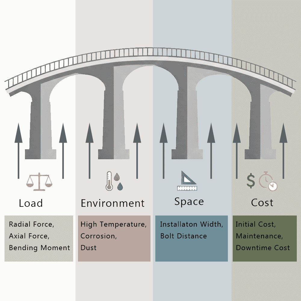
To move beyond "catalog checking" and into true engineering selection, we utilize the L.E.S.C. framework:
Quick Selection Logic:
The housing configuration is the foundation of your bearing's performance. Choosing the wrong bolt pattern can lead to premature failure.
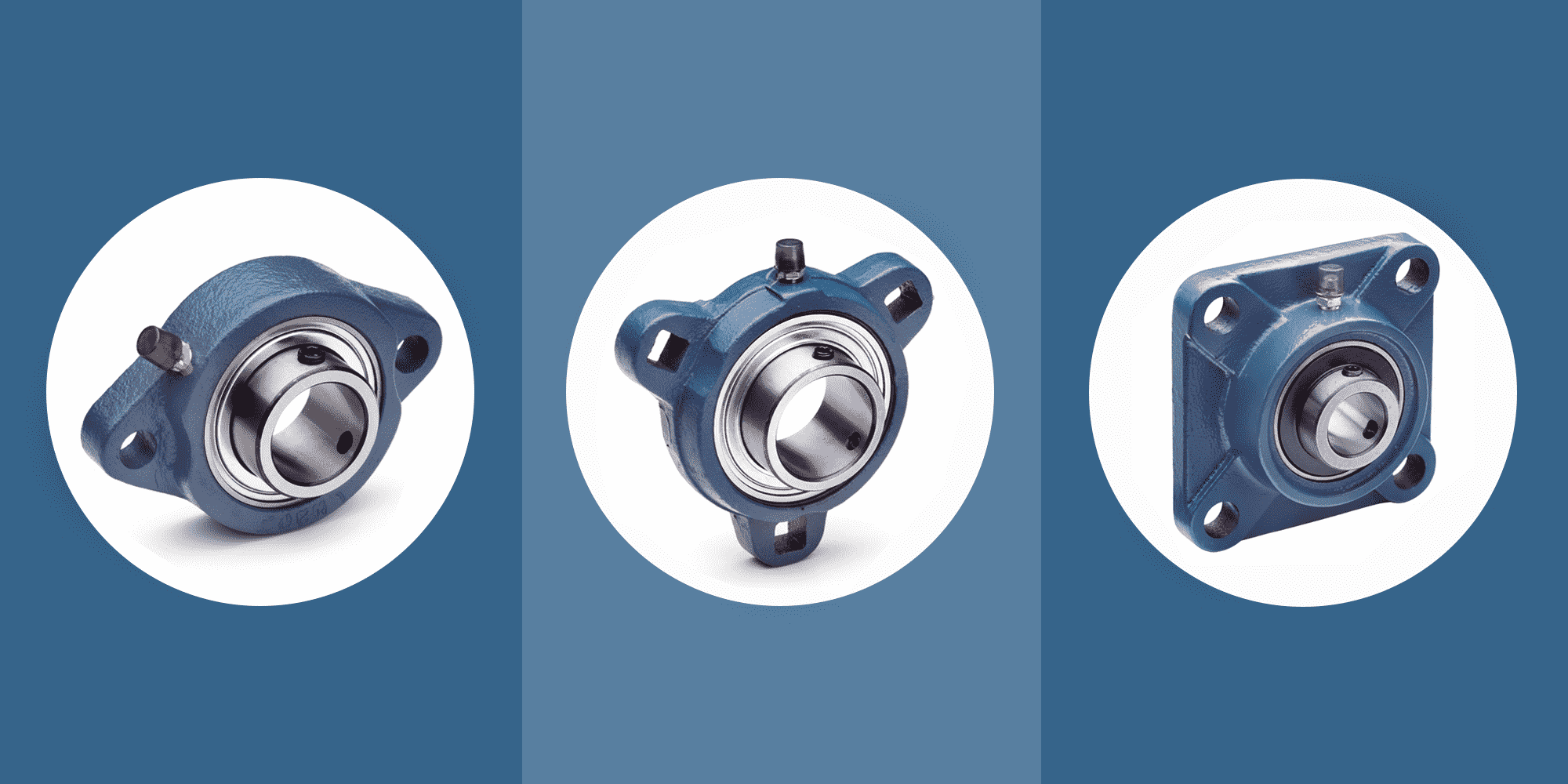
The UCFL series features a compact, diamond-shaped footprint ideal for narrow machinery frames.

The UCF series is the industrial standard for maximum structural rigidity and vibration resistance.

These provides offset stability specifically for vertical plate mounting.

Engineering Quick Rule (Based on Field Data):
Loads >5kN or shock/vibration → 4-bolt (UCF series)
Space-critical + loads <3kN → 2-bolt (UCFL series)
Vertical mounting or asymmetric loads → 3-bolt (UCFT series)
Once the housing is determined, the internal bearing type must match your operational data.
Most flanged bearings use ball or roller inserts.
However, some specific low-speed applications sometimes use plain bearings—these reduce friction without rolling elements.
Ball bearing inserts are best for high speeds. For example, a ⌀40mm shaft at 3,000 RPM results in a d*n factor of 120,000, making ball bearings the primary choice.

Consider radial load index (Fr / C0r).
If radial load (Fr) is 5 KN and the bearing's static capacity (C0r) is 40 KN, the index is 0.125.
Since this exceeds 0.1, a transition to roller bearings is highly recommended.

The shaft-to-insert connection determines whether your bearing stays put or develops fretting corrosion from micro-movement.
Three mechanisms dominate the market, each suited to specific conditions.
Quick installation for loads under 3KN, but creates an indentation on the shaft surface.
Acceptable for non-critical applications where shaft reuse isn't required.
Avoid in any vibration environment above 5 Hz—the screws will loosen.

The solution for vibration and reversing loads. The cam-action collar creates 360° shaft contact without surface damage.
Use this for any application with vibration exceeding 5 Hz, bi-directional rotation, or where shaft preservation matters.
Approximately 1.4x the cost of set screws, but eliminates the most common cause of premature bearing failure: shaft slip.

The gold standard for high-speed precision.
It uses a 360° squeeze mechanism to ensure the shaft center aligns perfectly with the bearing center.
This eliminates the eccentric imbalance of set screws, significantly reducing noise and vibration in high-RPM applications (e.g., HVAC fans).

Heavy-duty applications exceeding 8 kN demand adapter sleeves.
The tapered design with hydraulic locknut provides the highest clamping force and allows tool-free removal.
Essential for shafts over 50mm diameter or facilities where maintenance frequency justifies the 3x cost premium over set screws.

Selection checkpoint:
Housing material determines service life in harsh environments.
The wrong material choice here doesn't just cause premature failure.
It can lead to contamination issues in food processing or catastrophic fractures in high-impact applications.
Critical Notes:
The following decision tree provides a systematic method for narrowing down material options based on the primary environmental and operational drivers.
Use it as your first-step screening tool.

Cast iron bearing housings in a marine conveyor application typically fail from corrosion within 18 months, requiring complete replacement.
Stainless steel units in the same environment deliver 7+ years of service.
Break-even occurs after 2.1 replacement cycles—by year 3, stainless steel has paid for itself and continues providing value.
Factor in labor costs and production downtime, and the payback period often shrinks to under 2 years.
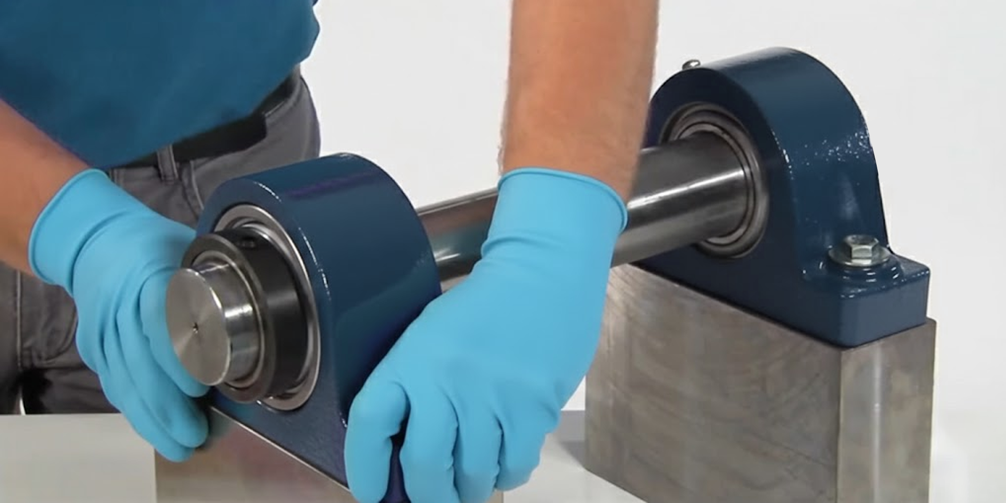
Proper installation determines whether your carefully specified flange bearing achieves its design life or fails prematurely.
The following checkpoints prevent 90% of installation-related failures.
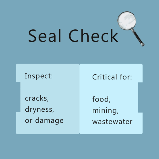
Inspect all seals—rubber lips, labyrinth designs, or contact seals—for cracks, dryness, or damage before installation.
In contaminated environments (food processing, mining, wastewater treatment), the bearing seal is your primary defense against bearing failure.
A damaged seal that costs $5 to replace will destroy a $200 bearing if missed during inspection.
Verify shaft tolerances match specifications (typically h6 or js6 tolerance grades).
Measure shaft diameter at multiple points and check surface planarity of the mounting base.
Out-of-tolerance shafts create interference problems, while warped mounting surfaces induce stress into the housing.

Use a dial indicator to validate shaft-to-surface verticality within 0.05mm per 100mm.
Angular misalignment creates edge loading that accelerates bearing wear and reduces service life by 40-60%.

Implement the star pattern tightening sequence for all multi-bolt housings.
This sequence ensures even load distribution and prevents housing distortion.
Reference manufacturer torque tables for specific values—these vary significantly based on bolt size, housing material, and application.
Under-tightening allows movement and fretting; over-tightening cracks housings or distorts bearing rings.
Use a calibrated torque wrench, not an impact gun.
Transition from time-based to condition-based maintenance by monitoring two key parameters:
Establish baseline vibration signatures during commissioning.
Schedule monitoring at regular intervals based on criticality—monthly for critical equipment, quarterly for standard applications.
Frequency spectrum changes indicate developing bearing defects before catastrophic failure.
Bearing temperatures exceeding 20°C above ambient indicate lubrication issues, contamination, or developing faults.
Thermal imaging during operation identifies hot bearings that require investigation.
These monitoring approaches catch problems early when a $200 bearing replacement prevents a $20,000 equipment failure.
Proper flange bearing selection prevents the specification errors that cause 90% of premature failures.
The L.E.S.C. framework—Load, Environment, Space, Cost—provides a systematic approach to matching configurations to actual operating conditions.
Match the configuration to your environment, verify mounting surfaces, and document your installation procedures.
Need help selecting the right bearing? Contact LILY Bearing's technical team for recommendations.
Or browse our complete mounted bearing catalog to find solutions for your equipment.

In the world of machinery, mounted bearings play a pivotal role. They are integral to the smooth operation of various equipment across industries. ...
Mounted bearings play a crucial role in various machinery and equipment. These versatile components support a rotating shaft and are essential for a...
In the industrial world, an unplanned shutdown is a maintenance manager’s worst nightmare. Consider this: Install a $50 mounted bearing with just ...