

 Robert
How to Install a Mounted Bearing Units: The Ultimate Professional Guide
Mounted bearing—often referred to as pillow blocks or flange units—are the unsung heroes of the industrial world. They support rotating shafts,...
In the industrial world, an unplanned shutdown is a maintenance manager’s worst nightmare.
Consider this: Install a $50 mounted bearing with just 0.02mm deviation—thinner than 1/3 of a human hair. That tiny error can trigger catastrophic failure: 48 hours of downtime and over $50,000 in lost production.

Industry statistics show one clear fact: 16% of premature bearing failures stem from avoidable mounting mistakes.
Follow this precision-engineered protocol and extend your equipment's life by up to 200%.
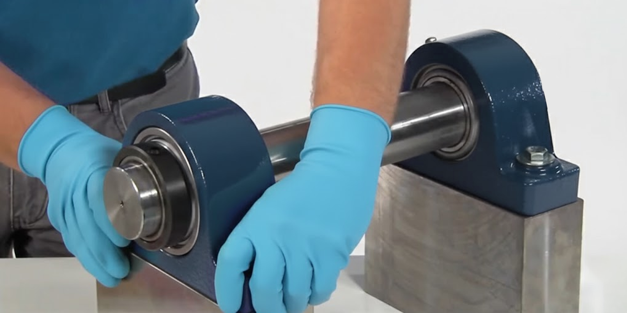
Reliability begins before the bearing ever touches the shaft.
Skipping preparation creates what engineers call a 'parasitic load'—destructive internal forces that overheat and destroy your bearing.
Never compromise on safety protocols. Mandatory PPE includes safety glasses and heavy-duty gloves.
Most importantly, ensure the power source is under a strict Lockout/Tagout (LOTO) procedure.
The "No Impact" Rule:
Never use air or impact tools on setscrews or adapter sleeves. The high-frequency shock can cause micro-fractures in the bearing raceway.
❌ Wrong: Using an electric impact wrench to "speed up" the job.
✅ Right: Utilizing a calibrated manual torque wrench for final seating.
Visual inspections are insufficient for high-speed applications.
You must use a micrometer to verify the shaft meets h7 tolerances—the industry standard for precision fit.
Why This Matters:
A food processing plant installed bearings on shafts measured with a tape measure.
One shaft was 0.03mm undersize—invisible to the eye but below h7 spec.
Inner ring movement destroyed the stainless steel shaft surface in just one week.
The result: a $12,000 emergency replacement and three days of downtime.
To prevent similar issues and ensure the longevity of your equipment, always adhere to these critical mounting steps:
Mounted bearings use four shaft attachment methods. Each has specific applications, limitations, and installation sequences.
Choosing the wrong method—or installing the right method incorrectly—is the leading cause of field failures.
Selecting the right locking method depends on your vibration levels and speed requirements.
This is the most common method—and most people do it in the wrong order.

The "Bolt-First" Rule—Non-Negotiable:
This is the most critical step in setscrew installation. The correct sequence is:


Why This Matters:
If you lock the inner ring before securing the housing, misalignment forces the bearing into a tilted position.
This creates what engineers call 'parasitic axial loading'—massive internal stress with two clear symptoms:
Reference torque values vary by screw size:
High-Vibration Applications:
In severe service environments (crushers, material handling, impact loading), consider these enhancements:
Common Mistakes—Avoid These:
Eccentric collars use cam action to lock the bearing to the shaft.
Conveyor systems use these because they absorb shock loads better than setscrews while installing faster than tapered sleeves.

Critical Limitation—Unidirectional Only:
Eccentric collars are designed for single-direction rotation.
The cam mechanism wedges tighter as the shaft rotates in the design direction.
Reverse the rotation, and the collar will unlock immediately, causing catastrophic failure.
Some applications reverse direction or rotate both ways. For these, use a tapered sleeve or concentric clamp collar.
Installation Sequence:

-1.png?width=386&height=386&name=Tighten%20the%20mounting%20bolts%20to%20the%20proper%20torque%20(Eccentric)-1.png)

-3.png?width=373&height=373&name=tighten%20the%20locking%20setscrew%20to%20the%20specified%20torque%20(Eccentric)-3.png)
The drift punch technique may seem crude, but it's essential. Hand-tightening alone won't generate sufficient interference.
Mechanically lock the collar before engaging the setscrew.
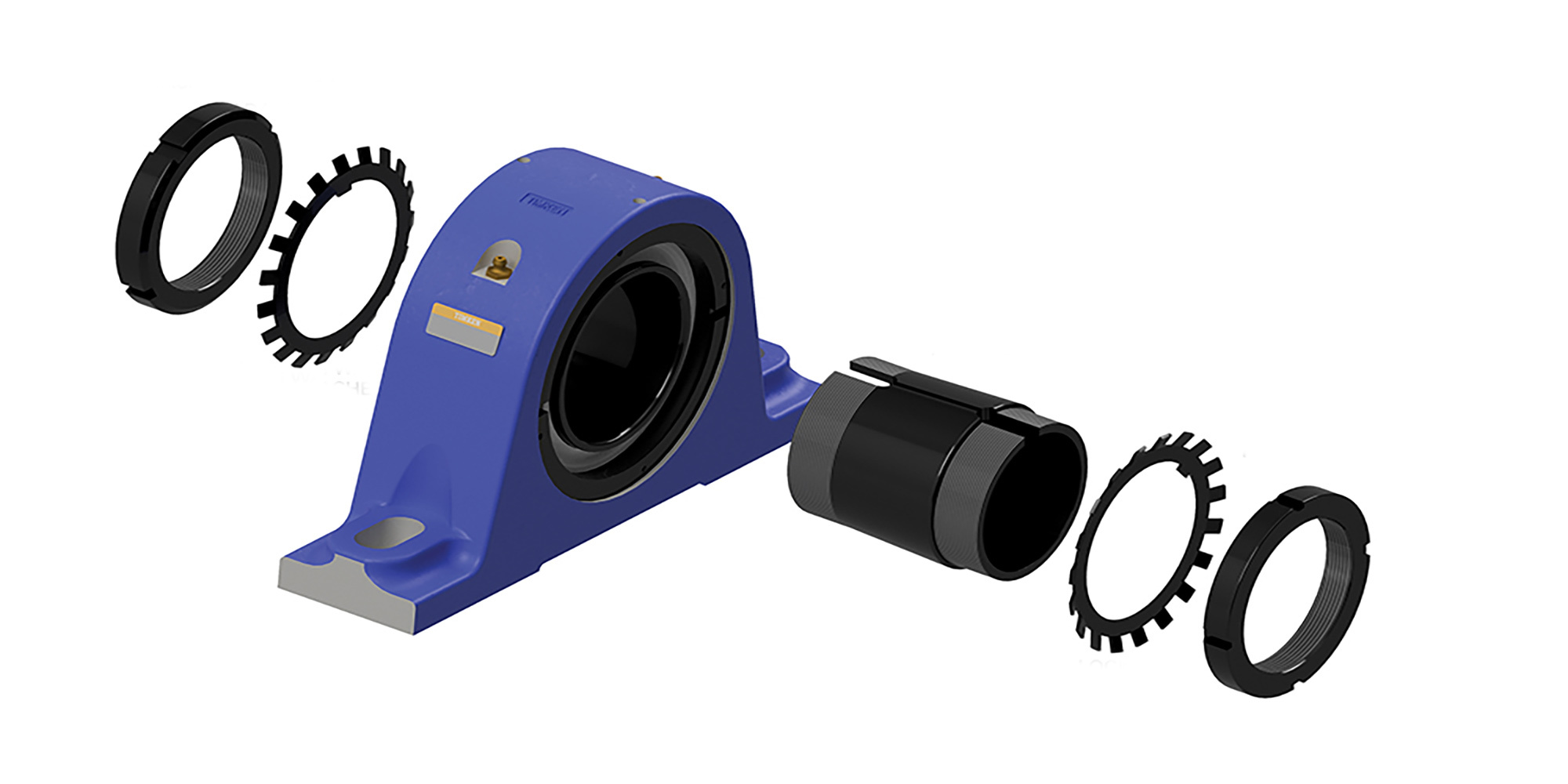
Tapered sleeves provide 360-degree concentric clamping with superior holding power.
Use them for precision applications, high speeds, and heavy radial or axial loads.

Note:
While reliable under impact and vibration, this unit is not suitable for shafts subjected to excessive axial loads.
Sleeve Positioning: Fit the adapter sleeve onto the shaft (large end first). For easier fitting, use a screwdriver to slightly expand the sleeve slot.
Bearing Installation: Slide the bearing unit over the sleeve and ensure the tapers align properly.-1.png?width=348&height=348&name=Bearing%20Installation%20(Tapered%20Adapter%20Sleeve)-1.png)
Housing Pre-tightening: Secure the housing bolts to the proper torque using washers.
Seating the Sleeve: Gently tap around the sleeve circumference to fully seat the bearing inner ring.

Washer & Nut Assembly: Place the lockwasher (inner tang toward bearing) and thread the locknut (chamfered face toward bearing). Hand-tighten the nut.

Final Locking: Use a hook spanner or a screwdriver/jig in the nut slots. Tap with a hammer until the nut rotates an additional 60° to 90°. Caution: Never tap the slinger and do not over-tighten.

Securing the Tabs: Bend the lockwasher tabs into the nut slots. If alignment is necessary, always rotate the nut forward; never back-rotate.

Final Housing Tightening: Fully tighten the mounting bolts to the specified torque.
Concentric clamp collars distribute clamping force evenly around the shaft circumference through multiple bolts.
Applications with hardened shafts, chrome plating, or frequent removal increasingly rely on these collars.
Advantages Over Setscrews:

Installation:
Tighten collar bolts in a star pattern (like torquing cylinder head bolts on an engine) to ensure even clamping.
Typical torque: 10-12 N⋅m for 50mm bore collars. Re-check torque after 24 hours of operation, as initial embedment may require slight re-tightening.
Limitation:
Concentric collars perform poorly in high-vibration environments because they rely on friction rather than mechanical interference.
For shock loading or severe vibration, use setscrews with flats or eccentric collars instead.
Steel expands approximately 12 microns per meter per degree Celsius (12 μm/m/°C).
On a 2-meter shaft operating with a 40°C temperature rise, the shaft will expand 0.96mm.
What happens when you rigidly fix both bearing positions? The shaft can't expand, so it bows. This creates side-loading that destroys bearings in weeks.
Implementation:
The floating end uses a bearing with cylindrical rollers (no shoulders) or a special housing that allows 2-3mm axial movement.
The fixed end uses a standard ball bearing or shouldered cylindrical roller bearing that constrains axial position.
Why float the non-drive end?
The motor coupling should remain in precise alignment.
Allowing the drive end to float would create coupling misalignment and vibration.
Float the far end instead, where axial position is less critical.
When installing a second bearing on the same shaft, never assume the mounting surfaces are coplanar.
Even precision-machined baseplates often have 0.1-0.2mm height variation that will preload the bearings if ignored.

The Shim Stock Method:
This ensures both bearings sit naturally on their mounting surfaces without being forced into alignment.
Forcing alignment creates preload that appears as elevated temperature and reduced life.
Verification:
After mounting both bearings, check that the shaft rotates freely by hand with no binding.
If you feel tight spots or the shaft won't rotate easily, there's preload in the system—check for shimming errors or housing misalignment.
Monitor the bearing during the first 30 minutes of operation.
World-class maintenance relies on Predictive Maintenance (PdM). Record the following data as a baseline:
Q: Can I reuse an old housing with a new bearing insert?
A: Not recommended. Housing bores can become "out-of-round" over time. This stops the new insert from self-aligning and leads to early failure.
Q: Why do my setscrews keep backing out?
A: This usually points to high vibration or an undersized shaft. Verify the shaft meets h7 specs and consider using a medium-strength anaerobic threadlocker.
Q: How do I choose between Fixed and Floating?
A: Refer to the Fixed vs. Floating Decision Tree in Step 3.1. It is the gold standard for managing thermal expansion in long-run shafts.
Q: Do I need to adjust torque for stainless steel shafts?
A: Yes. Stainless is softer (30 HRC vs 50 HRC for carbon steel). Reduce setscrew torque by 20-30% to prevent galling. Example: Use 6-7 N⋅m instead of 8.8 N⋅m for M8 setscrews.
Q: What's special about vertical shaft installations?
A: Gravity creates constant thrust loading—use angular contact bearings or add thrust washers. Use NLGI Grade 3 grease (resists downward migration) and apply threadlocker to all fasteners.
What separates a mounted bearing that reaches its rated L10 life from one that fails early?
Not exotic materials or advanced technology—but dimensional accuracy within 0.01mm, torque values within ±10%, and disciplined procedure during a 15-minute installation.
As one bearing manufacturer engineer put it: "We build bearings to last 5 years. Don't destroy them in 5 minutes of careless installation."
Need expert guidance on your next mounted bearing project? Contact our technical team.
Follow the engineering protocol, record your data, and protect your industrial assets.
Mounted bearing—often referred to as pillow blocks or flange units—are the unsung heroes of the industrial world. They support rotating shafts,...
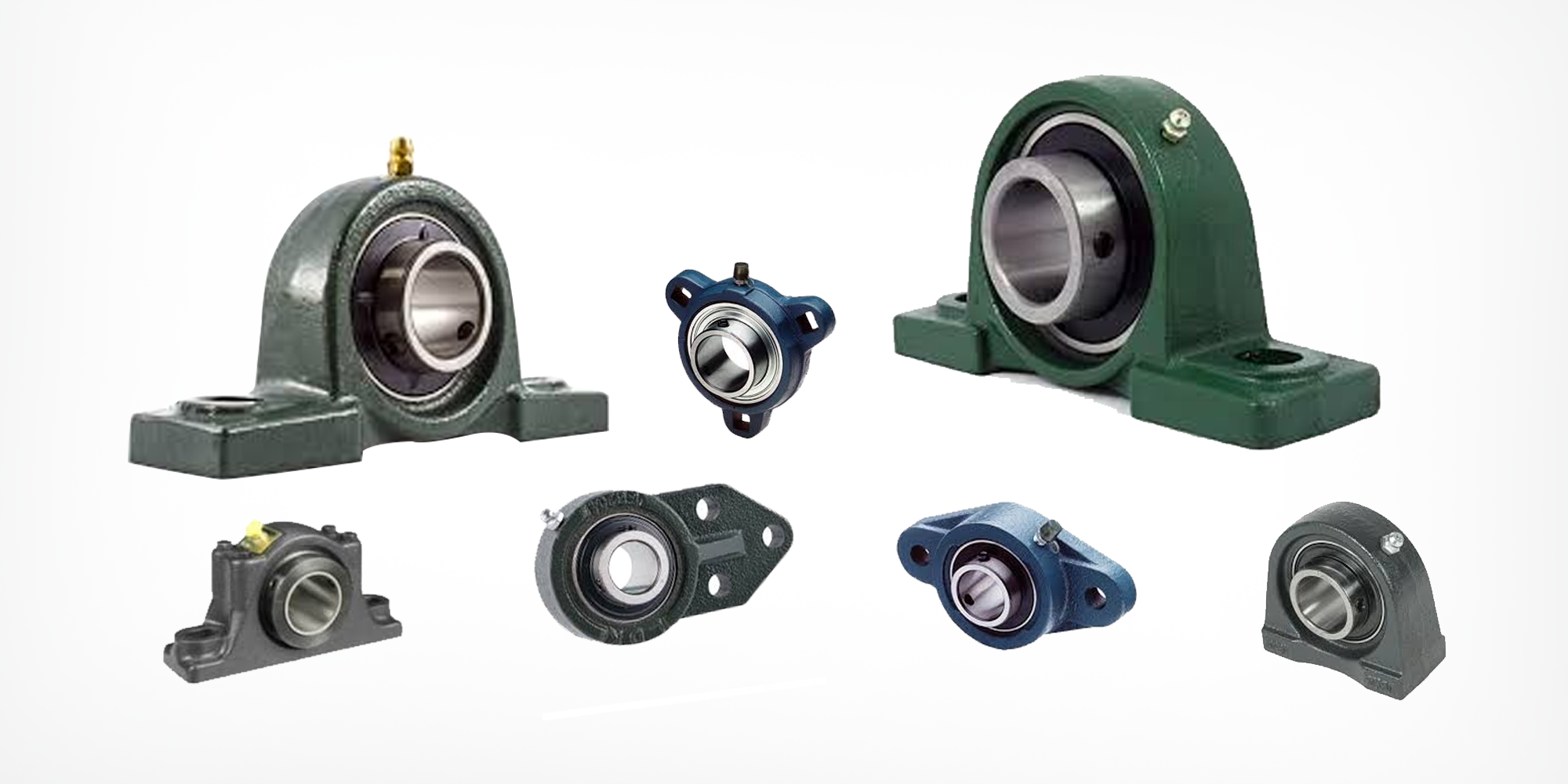
Mounted bearings play a crucial role in various machinery and equipment. These versatile components support a rotating shaft and are essential for a...
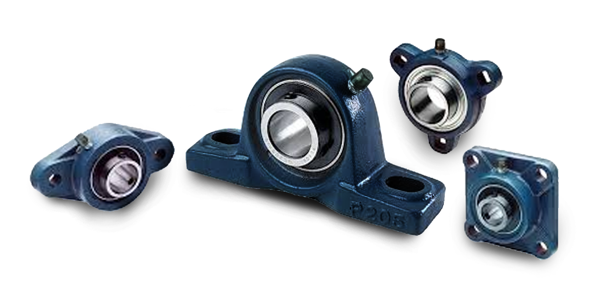
Mounted bearings are pre-assembled units that combine an insert bearing (such as a ball or roller bearing) with a housing. They are designed to...