

 Robert
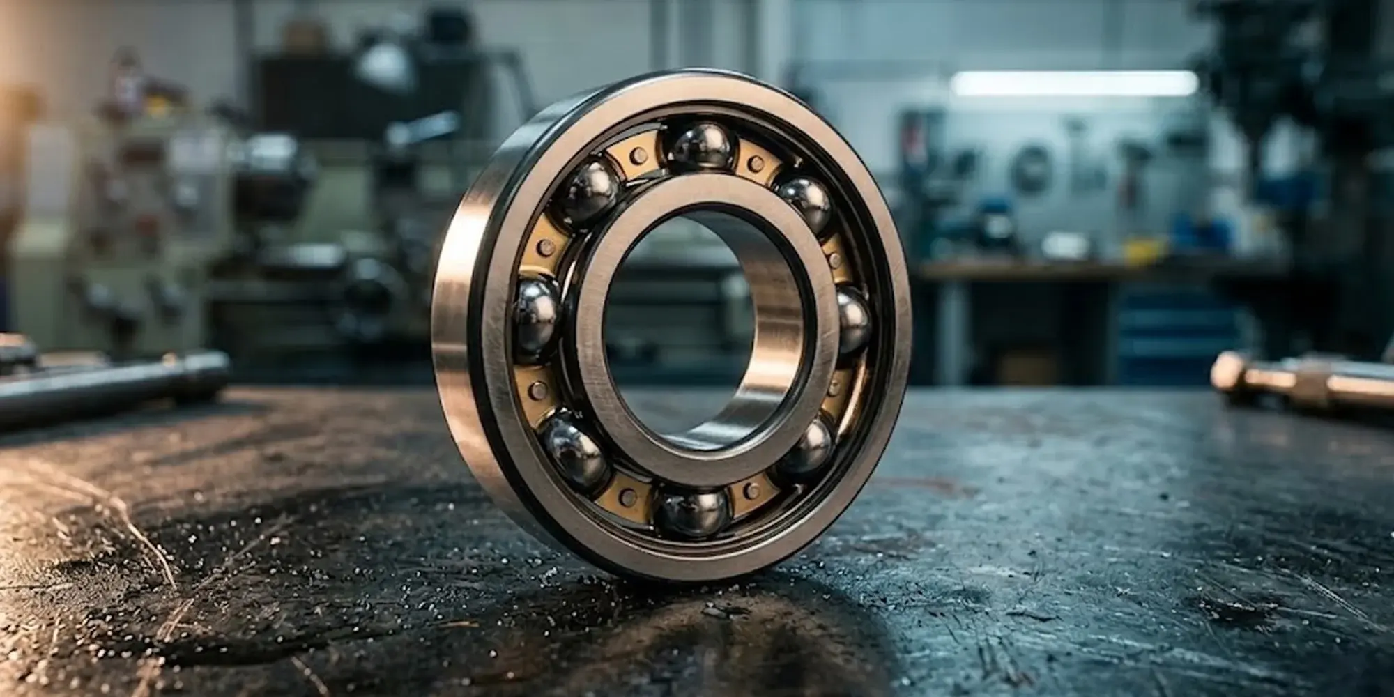
Bearing Size Chart Guide: Ball, Roller & Thrust Bearing Dimensions
What Is a Bearing Size Chart? A bearing size chart is a standardized reference table that maps bearing part numbers to their three core physical...
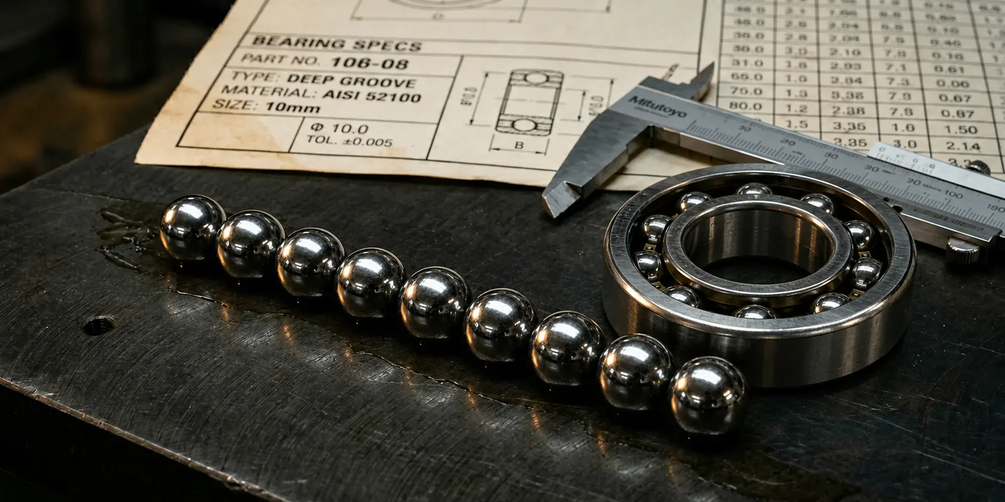
What Is a Bearing Size Chart? A bearing size chart is a standardized reference table that maps bearing part numbers to their three core physical...
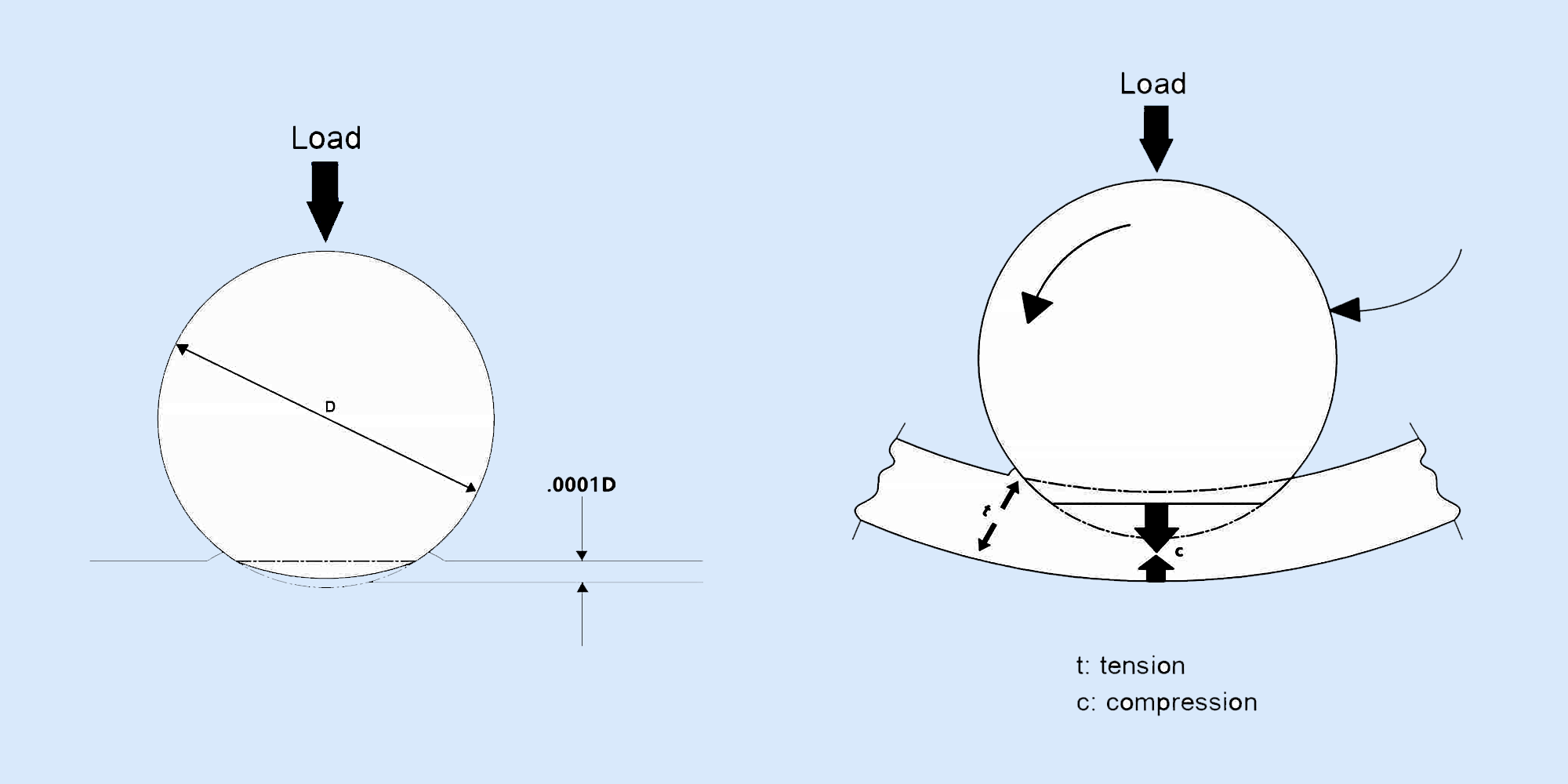
Bearings play a vital role in machinery by ensuring smooth motion and reducing friction. Understanding load capacities, specifically static load vs...
Four hundred hours into service — well short of its rated life — a conveyor drive assembly goes down. The maintenance team traces it back to a...