

A slewing bearing failure on a mobile crane costs an average of $50,000–$200,000 in downtime and replacement — yet many engineers make their initial selection based on diameter alone.
The right selection process considers at least six interdependent variables: load type, magnitude, rotational speed, precision requirements, environmental exposure, and gear configuration.
This guide walks through the full 9-step selection process used by LILY Bearing's engineering team, covering load calculation, service factors, gear sizing, mounting arrangements, and bearing series review.
Whether you are specifying a slewing ring for a crane, excavator, wind turbine, or industrial robot, every step here applies directly to your application.

What Is a Slewing Bearing?
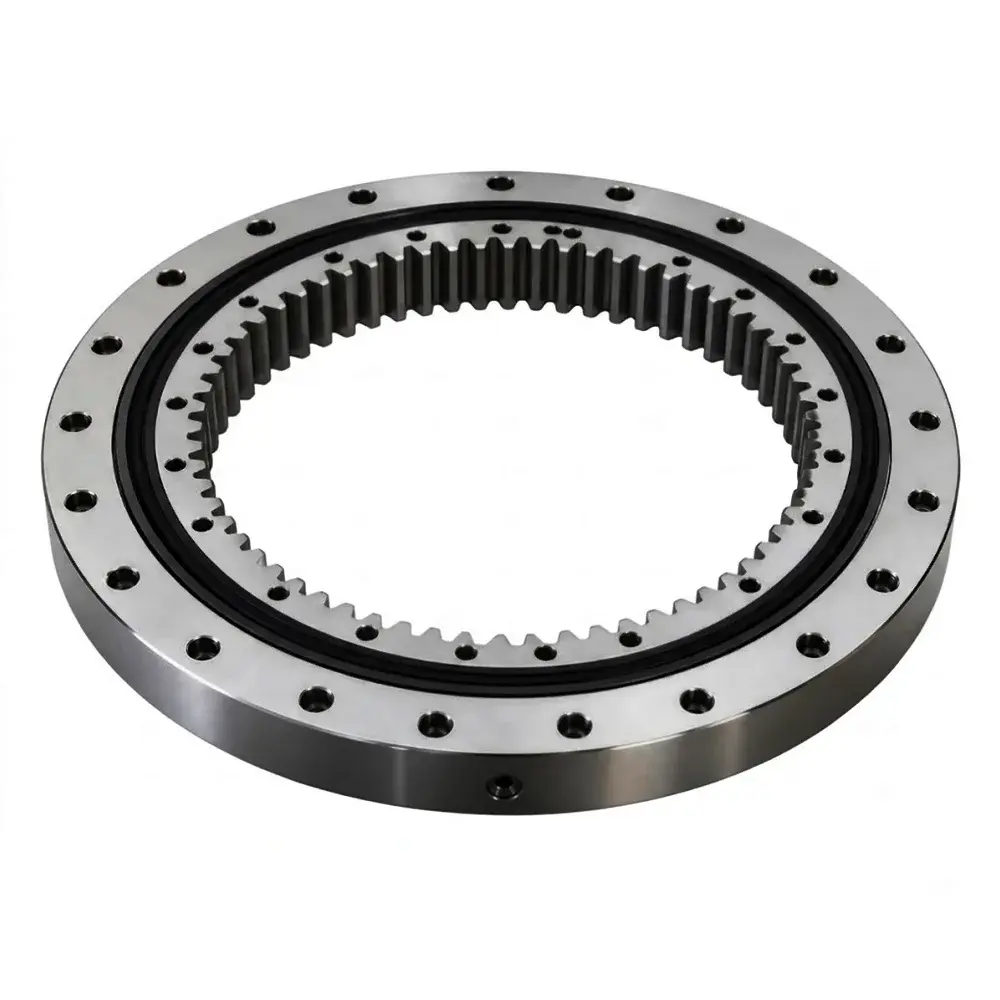
A slewing bearing — also called a slewing ring or turntable bearing — is a large-diameter rolling-element bearing designed to handle simultaneous axial loads, radial loads, and moment (tilting) loads while enabling continuous 360° rotation.
Unlike a standard deep-groove ball bearing that handles primarily one load direction, a slewing ring must manage all three load types at once, which is why selection is more complex and more consequential than most bearing decisions.
They range from around 100 mm in compact robotic joints to over 8,000 mm (315 inches) in offshore cranes and large industrial rotary tables.
Most include integrated gear teeth — either on the outer ring (external gear) or inner ring (internal gear) — for powered rotation via a mating pinion.

Slewing bearing components: inner/outer rings, rolling elements, spacers, seals, and mounting holes
Key Components
Inner & Outer Rings
Main structural elements housing the rolling elements between them
Rolling Elements
Balls or rollers that transfer load and enable smooth rotation
Spacers / Cages
Guide and separate rolling elements for even load distribution
Seals
Protect the raceway against dust, water, and contaminant ingress
Mounting Holes
Through-bolt or threaded patterns securing the bearing to the structure
Optional Gear Teeth
External or internal profile for pinion-driven rotation
Types of Slewing Bearings
Choosing the wrong bearing type is one of the most common — and costly — early mistakes in the selection process.
Each type has a distinct load profile, precision capability, and size range.
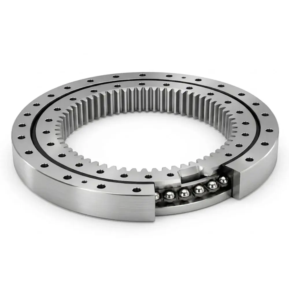
Each ball contacts the raceway at 4 points, allowing a single row to handle axial, radial, and moment loads simultaneously. The most common general-purpose choice for moderate, balanced loads.
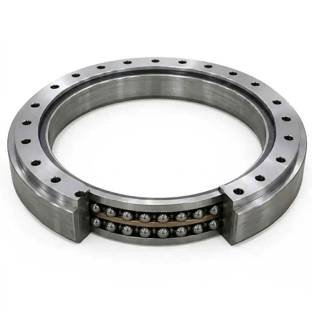
Two-row design doubling the contact points. Delivers higher load capacity and greater stiffness than the four-point type under heavy-duty axial and moment loads.
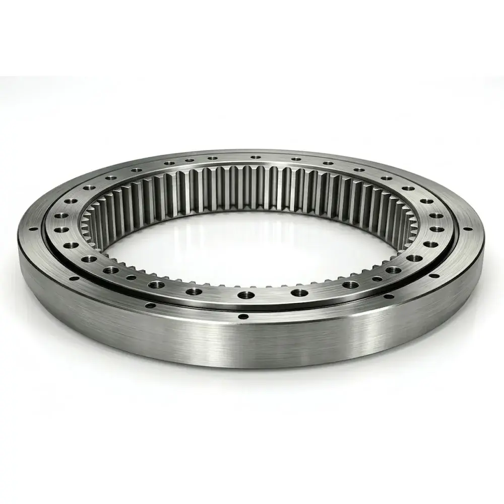
Cylindrical rollers arranged alternately at 90° carry all load types with high rigidity — typically to ISO tolerance class P5 or better. Preferred for robotics, medical imaging, and radar systems where positional accuracy is critical.
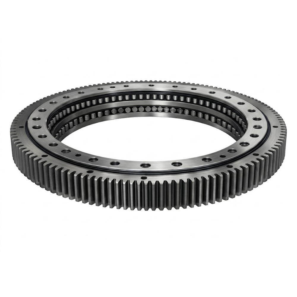
Separates the three load paths (axial up, axial down, radial) into dedicated roller rows. Delivers very high load capacity in a compact cross-section. Standard for large excavators and offshore cranes.
Designed primarily for high axial loads with limited moment capacity. Used in light turntables and indexing applications where tilting forces are minimal.
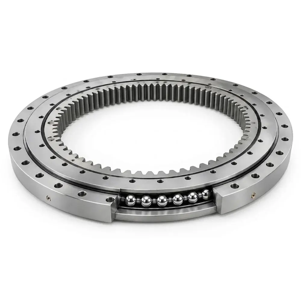
Pairs a ball row for axial/moment loads with roller rows for radial loads. Useful when radial loading is disproportionately high relative to axial loading.
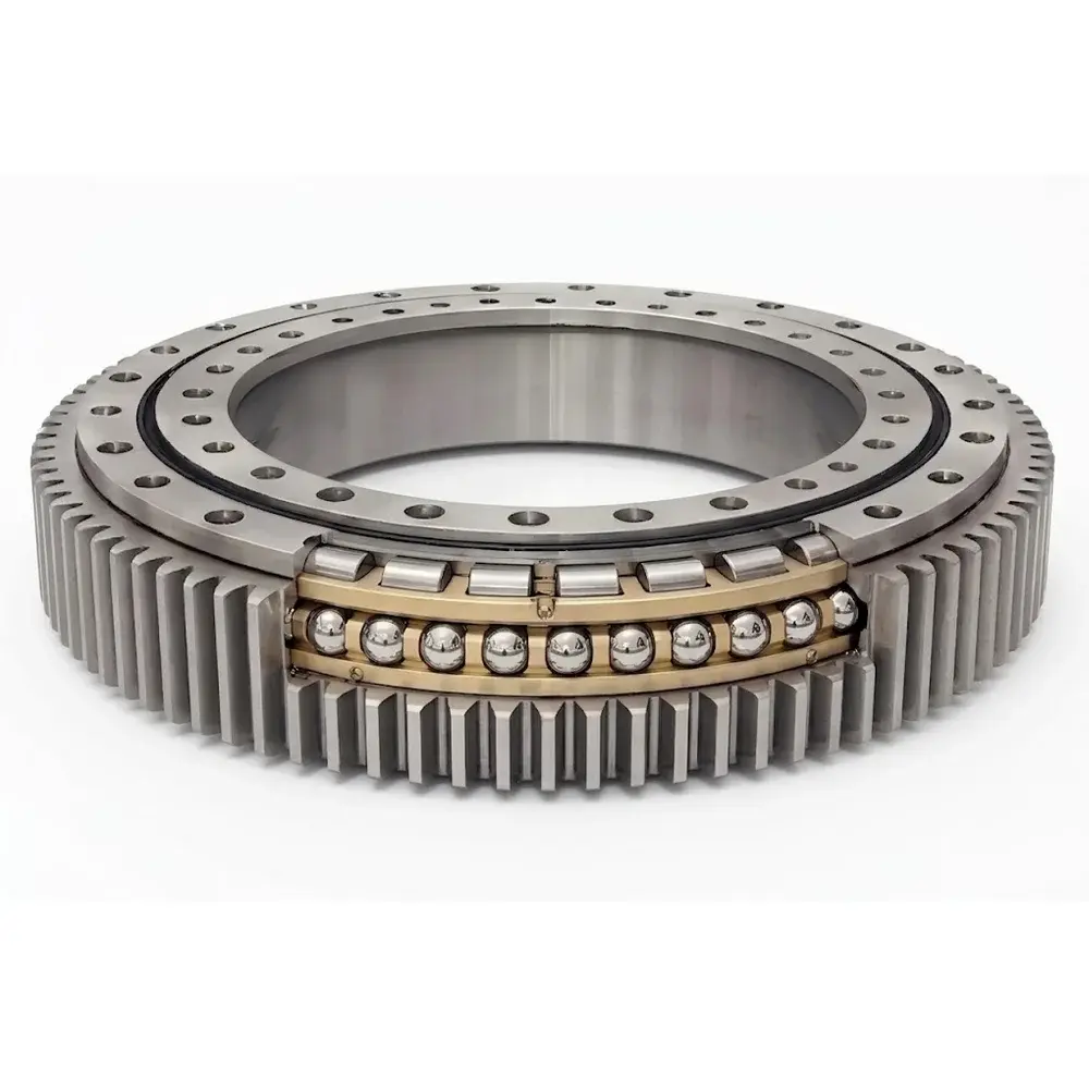
Thin-section design for space-constrained installations. Cross-sectional dimensions remain constant across a wide bore diameter range, making them ideal for lightweight automation and camera platforms.
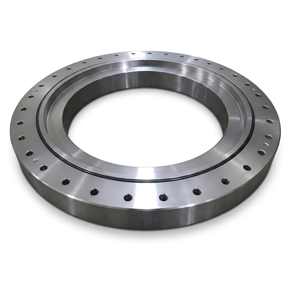
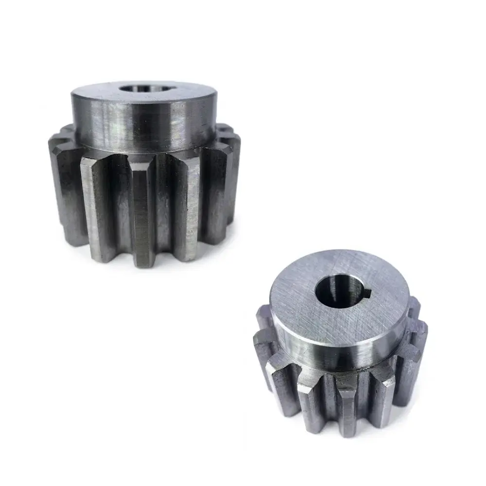
Drive components paired with geared slewing rings to enable powered rotation. Pinion geometry — module, tooth count, and face width — must be matched to the ring gear to ensure correct load distribution and acceptable backlash.
Slewing Ring Bearings for Transport Vehicles
Engineered for the specific load profiles of transport applications — including articulated vehicles, self-propelled modular transporters, and military platforms — where smooth rotation under dynamic road loads and compact packaging are both required.
Key Selection Factors
Before running calculations, understand the five factors that govern every slewing bearing selection decision.
5 Factors That Govern Slewing Bearing Selection
1 Load Type & Magnitude
Axial, radial, and moment loads must each be quantified. Underestimating any one of them is the leading cause of premature bearing failure.
2 Rotational Speed
Most slewing bearings operate at 0.1–10 RPM. Higher speeds require lower contact stress levels and may necessitate a revised lubrication schedule or different seal type.
3 Required Precision
Standard crane applications typically require P0 (normal) tolerance. Robotic arms, medical CT gantries, and radar antennas may require P5 or P4 — a specification that significantly narrows available options.
4 Environmental Conditions
Operating temperature range, humidity, dust, saltwater exposure, and chemical contact all affect seal type, coating, and lubricant selection. Offshore applications typically require additional corrosion protection.
5 Space & Mounting Constraints
Available envelope dimensions, required bolt pattern, and structural interface determine which cross-sections are physically viable before load capacity is even evaluated.
The 9-Step Selection Process
This is the same structured process LILY Bearing's engineers use when reviewing custom applications.
Work through every step — skipping ahead often results in a bearing that looks right on paper but fails in service.
Step 1: Identify Equipment Requirements
Start by documenting the full operating envelope. Every parameter you fail to capture here creates a risk downstream. At minimum, record:
- Axis of rotation: horizontal, vertical, or alternating
- Movement type: positioning only, slewing, or continuous rotation
- Maximum and average axial, radial, and moment loads (kN / kN·m)
- Maximum and average rotational speed (RPM)
- Required positional accuracy and runout tolerance
- Operating temperature range (min / max °C)
- Exposure conditions: humidity, dust, salt, chemicals
- Design service life (hours or cycles)
- Available installation envelope (OD, ID, height)
- Budget and target cost of ownership
Step 2: Calculate Maximum Bearing Loads
Determine both static and dynamic peak loads, then reduce them to the three equivalent forces acting at the bearing center: axial force Fa, radial force Fr, and overturning moment M.
Do not limit your analysis to rated working conditions — account for:
Emergency stop and brake torque events
Overload test conditions (typically 125% of rated load per relevant standards)
Extreme wind loading for cranes and wind turbines
Assembly and disassembly forces
The governing load case — not the typical operating case — determines your bearing size.
Step 3: Apply Service Factors
Multiply your calculated bearing forces by the appropriate service factor (fs) to account for dynamic effects, impact loading, and duty cycle.
The table below is the industry-standard reference used by most slewing bearing manufacturers.
If your application is not listed, use the closest analogous category, or consult the manufacturer directly.
Application | fs |
|---|---|
Aerial Lift Devices | |
Aerial baskets, platforms, ladders | 1.00 |
Conveyors | |
General conveyor applications | 1.00 |
Cranes — Mobile (load limited by machine stability) | |
Normal construction duty, tire mounted | 1.00 |
Normal construction duty, crawler mounted | 1.10 |
Production duty (scrap / ship yards) | 1.25 |
Forestry / logging | 1.50 |
Stacker cranes (includes dynamic forces as loads) | 1.25 |
Cranes — Pedestal / Tower (loads not limited by machine stability) | |
Loads monitored by safe load device | 1.25 |
Applications with sudden impact load | 1.50 |
Excavators | |
Load limited by tipping | 1.25 |
Load limited by hydraulic pressure relief | 1.50 |
Index & Turnstile Tables | |
Occasional use, intermittent rotation | 1.00 |
Frequent use, intermittent rotation | 1.25 |
Frequent use, intermittent rotation with impact | 1.50 |
Industrial Manipulators & Robots | |
Occasional service | 1.00 |
Frequent service | 1.25 |
Steering Gear (must include dynamic and shock loads) | |
Pneumatic tires | 1.25 |
Solid tires | 1.50 |
Step 4: Determine Gear Requirements
If powered rotation is required, specify gear capacity early — it drives the ring geometry.
Define required output torque, duty cycle, and gear quality class (AGMA 2001 or ISO 1328). Consider:
Peak torque under dynamic vs. static conditions
Torque demands on inclines or under wind loading
Overload test torque requirements
Allowable backlash range for positioning accuracy
Module and tooth count relative to mating pinion geometry
Step 5: Select Mounting Arrangement
The mounting configuration determines which ring rotates, where the pinion sits, and how the bearing is secured.
LILY Bearing's four standard arrangements cover the majority of applications:
Fig. 1 — Outer ring rotates, inner ring fixed (through bolt)

The pinion attaches to the outer ring, which supports the upper structure. The inner ring is fixed to the lower structure via through bolts. A contamination shroud covers the outer seal. Common on mobile cranes.
Fig. 2 — Inner ring rotates with upper structure, outer ring fixed (external gear, through bolt)

The upper structure and pinion are supported by the inner ring through bolts. The outer ring, carrying the gear teeth, is anchored to the lower structure with threaded bolts. An external shroud protects the gear.
Fig. 3 — Pinion on outer ring, internal gear on inner ring (threaded bolt)

The pinion connects to the upper structure, supported by the outer ring. Placing the gear on the inner ring shields it from harsh conditions — a good choice for abrasive outdoor environments. Secured by threaded bolts.
Fig. 4 — Pinion on lower structure, geared outer ring supports upper structure

The pinion attaches to the lower structure. The geared outer race holds the upper structure. Inner ring: through bolts. Outer ring: threaded bolts. Used in pedestal cranes and certain construction equipment.
Step 6: Review Bearing Series & Cross-Sections
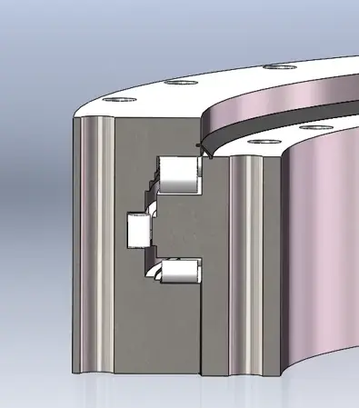
LILY Bearing's four main slewing ring series cover the full range from general-purpose industrial to extreme heavy-duty offshore applications:
RK Series
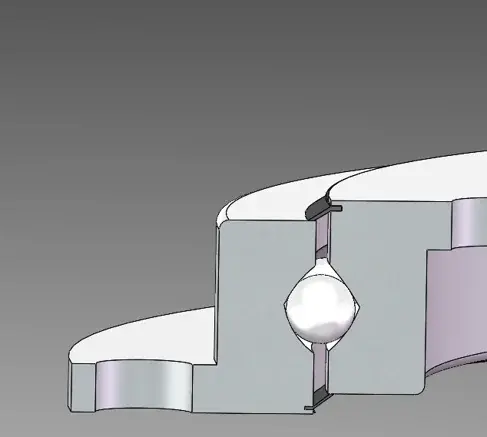
The RK Series are available in geared and non-geared variants ranging from 20" to 47" OD, supporting up to 141,000 ft-lbs moment, 175,000 lbs thrust, and 35,000 lbs radial loads.
MT Series
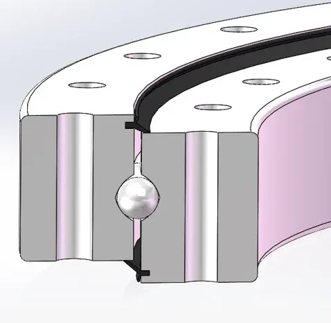
MT Series are available up to 240" OD with moment capacities up to 10,000,000 ft-lbs, thrust up to 6,000,000 lbs, and radial loads up to 1,300,000 lbs.
XR Series
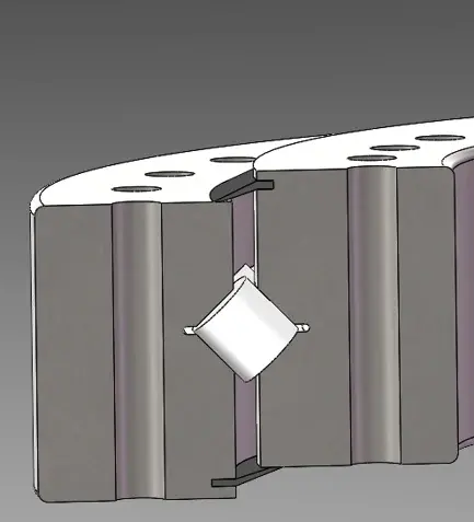
XR Series are available in sizes up to 315" OD, in internal, external, or non-geared versions.
TR Series
TR Series are available in sizes up to 315" OD with moment capacities exceeding 50,000,000 ft-lbs, thrust over 18,000,000 lbs, and radial loads above 4,000,000 lbs, in internal, external, or non-geared configurations.
Step 7: Preliminary Selection Against the Rating Curve
Plot your factored load combinations (Fa × fs, M × fs) against the bearing's published rating curve.
All operating load combinations must fall below the curve. Three additional rules apply:
Extreme (rare static) loads must also fall below the curve — the service factor may be excluded only if such loads occur fewer than 10 times in the bearing's design life
All normal dynamic loads must be plotted with the full service factor applied
Maximum thrust rating must exceed 3× the maximum operating thrust force — this is a hard minimum, not a guideline

Bearing rating curve: all operating load combinations must fall below the curve
Step 8: Gear Size & Quality Verification
Verify gear geometry and quality class against torque requirements and applicable standards.
Key checks:
Module and face width: must match torque demand and available envelope
Material and case hardness: LILY Bearing induction-hardens gear teeth to HRC 50–60
Quality class: confirm AGMA 2001 or ISO 1328 class matches the accuracy requirements
Backlash: confirm allowable backlash is compatible with positioning requirements
Mating pinion tooth count: >17 teeth recommended to minimize wear concentration on the ring gear
Step 9: Final Confirmation
Before releasing the specification, confirm the selected bearing satisfies every original requirement from Step 1:
- Load capacity — all three load types, all load cases ✓
- Speed rating ✓
- Precision / runout tolerance ✓
- Environmental protection — seal type, coating, lubricant ✓
- Gear capacity and quality class ✓
- Mounting arrangement and bolt pattern ✓
- Physical envelope (OD, ID, height) ✓
- Service life target ✓
External Gear vs. Internal Gear: Which Do You Need?
Gear location affects pinion accessibility, contamination exposure, structural clearance, and the torque output of the drive system.
This decision is frequently misunderstood and often made too late in the design process.
External Gear
Advantages
- Larger pitch diameter → higher torque output for a given module
- Pinion installation and inspection without disassembling the upper structure
- Lower manufacturing cost in most standard configurations
Limitations
- Gear teeth fully exposed — requires a shroud in dusty, abrasive, or corrosive environments
- Larger overall OD for the same ring size
Typical use: Mobile cranes, tower cranes, excavators, wind turbine pitch and yaw drives
Internal Gear
Advantages
- Gear teeth protected inside the ring — significantly better contamination resistance
- Smaller OD for the same pitch diameter; more compact installation envelope
- Preferred for wash-down and clean-room environments
Limitations
- Pinion must enter from below or through the structure — maintenance access more constrained
- Higher manufacturing complexity, typically higher unit cost
Typical use: Industrial robots, medical imaging gantries, radar/antenna systems, precision turntables
For external gear applications in abrasive environments — logging cranes and port equipment are the most common examples — always specify a protective shroud over the gear teeth.
Missing or degraded gear protection is among the top three causes of premature slewing bearing wear in outdoor service.
Application-Specific Guidance
Load profiles and dominant failure modes differ significantly by equipment type. The most critical selection criteria for five common applications:
Materials & Manufacturing
Ring Material
Inner and outer rings are manufactured from medium-carbon or alloy steel. LILY Bearing uses three primary materials depending on the applicable standard and load requirements:
Property | 42CrMo4 (1.7225) | 50Mn (GB/T 699) | 42CrMo (GB/T 3077) |
|---|---|---|---|
Yield Strength | ≥ 930 MPa | ≥ 390 MPa | ≥ 930 MPa |
Tensile Strength | ≥ 1,080 MPa | ≥ 645 MPa | ≥ 1,080 MPa |
Elongation | ≥ 12% | ≥ 13% | ≥ 12% |
Annealed Hardness | ≤ 217 HB | ≤ 217 HB | ≤ 217 HB |
Best For | High-strength, European-standard projects | Cost-efficient standard-duty | High-strength, Chinese-standard projects |
Raceway Heat Treatment
LILY Bearing applies selective induction hardening to the raceways, achieving a surface hardness of HRC 50–60 while leaving the core tough and ductile. This prevents the three primary raceway failure modes:
Abrasive wear — from contamination or inadequate lubrication
Rolling contact fatigue — subsurface crack propagation under cyclic Hertzian stress
Corrosion pitting — from moisture ingress through degraded seals
Lubrication
For most applications operating between −20°C and 120°C, LILY Bearing recommends No. 2 lithium ester grease. In standard industrial service, relubrication every 250–500 operating hours is a common starting point. Adjust the interval based on:
Actual operating temperature (not just ambient)
Load magnitude and contact stress
Rotational speed
Degree of environmental contamination
High-temperature or heavily contaminated environments may require relubrication every 100 hours or less.
Frequently Asked Questions
What is the difference between a slewing bearing and a slewing ring?
The terms are interchangeable. "Slewing ring" generally refers to the complete assembly including the ring structure, rolling elements, seals, and any integrated gear. "Slewing bearing" more often refers to the bearing function itself. Both terms describe the same product category.
What causes slewing bearing failure?
The four most common causes are: inadequate or contaminated lubrication, overloading beyond the bearing's rated capacity, improper mounting (insufficient structural stiffness or uneven bolt preload), and water or abrasive ingress through damaged seals. Fretting corrosion from oscillating motion without full rotation is also frequently observed in wind turbine yaw applications.
What service factor should I apply for an excavator?
Use fs = 1.25 when the load is limited by machine tipping stability, and fs = 1.50 when it is limited by hydraulic pressure relief. The higher value accounts for impact and shock loading during bucket breakout and sudden slewing stops, which are the dominant load events in excavator duty cycles.
How do I verify that a slewing bearing is correctly sized?
Plot all factored load combinations on the manufacturer's rating curve and confirm they fall below it. Additionally, verify that the bearing's maximum thrust rating is at least 3× the maximum operating thrust force. If any load combination exceeds the curve, move to the next larger size or higher-capacity series and repeat the check.
When should I choose a three-row roller design over a single-row ball design?
When moment loads and thrust loads are both very high and a compact cross-section is required — typically in large excavators, offshore pedestal cranes, and tunnel boring machines. The three-row cross roller design (TR series) separates the three load paths into dedicated roller rows, enabling substantially higher capacity than any single-row configuration at the same OD.
How often should a slewing bearing be relubricated?
Every 250–500 operating hours in standard industrial service. High-temperature, heavily loaded, or contaminated environments may require intervals as short as 100 hours. Over-greasing is as harmful as under-lubrication — it can damage seals and cause churning losses. Always follow the manufacturer's recommendation for the specific application.
Need help selecting the right bearing?
LILY Bearing's engineering team reviews load calculations and provides bearing recommendations. Send your specifications and we will respond within one business day.
About the Author


