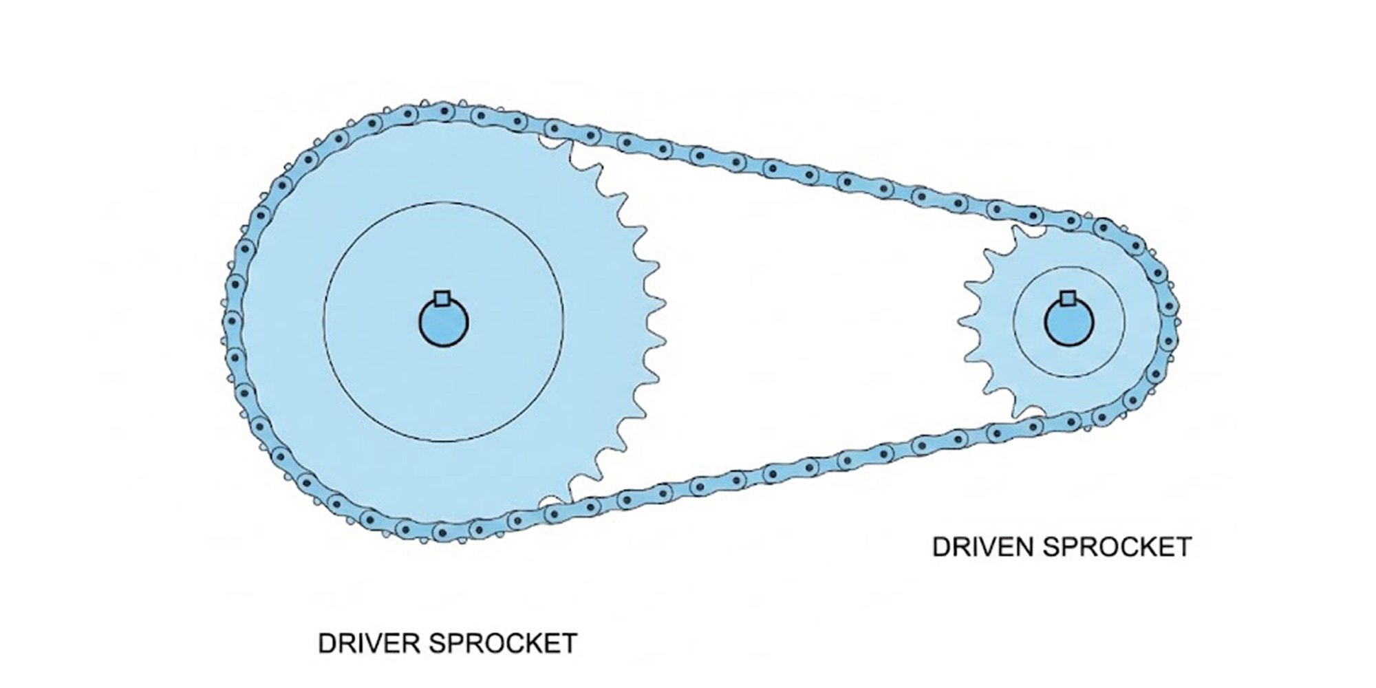
Motorcycle Sprocket Calculator — Gear Ratio & Top Speed
Changing the rear sprocket by 2 teeth on a 150cc commuter moves the final drive ratio by roughly 5% — noticeable in how the bike pulls out of...
Pick the wrong sprocket ratio and the chain speed climbs past the lubrication window — on a #40 drive that threshold is around 1,300 ft/min under oil-bath conditions.
Miss it, and roller fatigue sets in long before the chain reaches its rated service life.
The calculators above cover ratio, output speed, and chain length. Here is the engineering behind each one.
The gear ratio governs output speed, torque multiplication, and chain load in a single number. The formula:
Gear Ratio
Ratio = N₂ ÷ N₁
N₁ = driver (input) teeth · N₂ = driven (output) teeth
A 19T driver paired with a 38T driven sprocket gives 2.00:1 — the output shaft turns once per two input revolutions, torque doubles, speed halves. Swap to a 57T driven and the ratio becomes 3.00:1: torque triples, speed drops to one-third.
Worth knowing: adding one tooth to the driver shifts the ratio more than adding one tooth to the driven — by a factor roughly equal to the current ratio itself, because the driver is smaller and each tooth represents a larger percentage of the total. Use the driver for large adjustments, the driven for fine-tuning.
Ratio Reference Table — #40 Chain, 1,750 RPM Input
Chain speed = Driver teeth × 0.500″ pitch × 1,750 RPM ÷ 12. Verify against your actual chain pitch.
Two equations cover everything in Tab 2:
Output RPM
n₂ = n₁ × (N₁ ÷ N₂)
n₁ = input RPM
Chain Speed (ft/min)
V = (N₁ × p × n₁) ÷ 12
p = pitch in inches
Chain speed is the number most engineers skip until a chain fails early.
The Tab 2 calculator flags when you exceed the recommended limit for the selected chain size.
Those limits come from ANSI B29.1 and assume continuous oil-bath or drip lubrication — the most common setup for industrial drives running above 300 RPM.
If your system uses manual grease lubrication, reduce the limits below by roughly 25%.
Max Recommended Chain Speed — Continuous Oil-Bath Lubrication (ANSI B29.1)
Per ANSI B29.1 for standard single-strand roller chain with continuous lubrication. For manual greasing, apply a 25% reduction. Source: ASME B29.1.
The chain length formula in ISO 606 and ANSI B29.1 gives the number of links for a given center distance:
L = 2C/p + (N₂+N₁)/2 + (N₂−N₁)² ÷ (4π²·C/p)
L = links · C = center distance (in) · p = pitch (in) · N₁ = driver teeth · N₂ = driven teeth
Round the result up to the nearest even number.
An odd link count forces an offset (half) link, which reduces the chain's rated tensile strength by roughly 20% — a meaningful penalty on any drive running close to its load limit.
ANSI B29.1 recommends keeping center distance between 30× and 50× the chain pitch.
At 30× pitch, chain wrap on the smaller sprocket stays above the 120° minimum. At 50× pitch, the span is long enough to damp shock loads.
Order 2–3% extra chain length to give the tensioner room as the chain stretches during break-in.
When both sprockets share a common factor — 20T and 40T, for instance — the same chain links engage the same teeth on every revolution.
Wear concentrates on those contact points and service life falls sharply.
Switching to 19T/38T eliminates the problem: GCD is 19, so the chain cycles through all teeth before any link repeats.
A prime-number driver — 17T, 19T, 23T — is even better: it shares no common factor with any even-tooth driven sprocket, distributing load across the full tooth set.
✗ Avoid
20T / 40T
GCD = 20. Same links always hit the same teeth. Concentrated wear, shorter service life.
✓ Preferred
19T / 38T
GCD = 19. Every link touches every tooth before repeating. Even load distribution.
Chain pitch and standard must match exactly
ANSI and ISO/BS sprockets with the same pitch number use different tooth profiles and roller diameters. Mixing them causes the chain to seat incorrectly, producing rapid tooth wear and noise. Confirm the standard — ANSI (inch) or metric — before ordering.
Minimum 17 teeth on the driver above 500 RPM
Below 17T, the angle each chain link articulates through at engagement becomes large enough to cause measurable chordal action — a cyclical speed variation that generates vibration and accelerates roller wear. ANSI B29.1 calls out 17T as the practical floor for smooth high-speed operation.
Material hardness for the operating speed
Drives above 500 RPM call for induction-hardened carbon steel (HRC 40–50). Below 500 RPM at moderate loads, plain C45 carbon steel is sufficient. Grade 316 stainless handles corrosive environments but carries roughly 15–20% lower fatigue strength than hardened carbon — account for that in the load calculation.
Need ANSI or Metric Sprockets?
LILY Bearing stocks 9,500+ sprockets — ANSI, metric, miniature, idler, and bushing-bore. Same-day quotation on standard sizes.
Browse Sprocket CatalogANSI B29.1 places the practical limit at 7:1 for a single-stage roller chain drive. Above that ratio, chain wrap on the driver sprocket drops below 120°, increasing the impact load per tooth and shortening both chain and sprocket life. If your application needs a ratio above 7:1, use a two-stage drive with an intermediate shaft and split the ratio between the two stages.
Chain speed depends only on the driver side: V (ft/min) = N₁ × p × n₁ ÷ 12, where N₁ is driver tooth count, p is pitch in inches, and n₁ is input RPM. You don't need the driven sprocket teeth for this — just driver tooth count, pitch, and motor RPM.
No. ANSI (inch) and ISO/DIN metric sprockets with the same pitch number have different tooth profiles and roller diameter specifications. Running them together causes the chain to seat incorrectly — it rides high on the teeth, generating abnormal wear, noise, and eventual chain jump. Always match the chain standard to the sprocket standard across the entire drive.
The formula outputs a precise decimal; rounding it to the nearest integer often gives an odd result. The calculator already rounds up to the nearest even number automatically. If your physical setup forces an odd link count, you'll need an offset (half) link — this reduces the chain's rated tensile strength by approximately 20%, so avoid it on heavily loaded drives.
Gear ratio and output RPM are exact — no approximation involved. The chain length formula follows ANSI B29.1 and is accurate to within ±1 link for standard center distances. For precision machinery or drives running above 1,000 ft/min, confirm the calculated length with a physical trial assembly before cutting chain to final length.
Calculating sprocket ratios for a motorcycle? See our Motorcycle Sprocket Calculator for final drive ratio, estimated top speed, and per-bike gearing tables.
Changing the rear sprocket by 2 teeth on a 150cc commuter moves the final drive ratio by roughly 5% — noticeable in how the bike pulls out of...
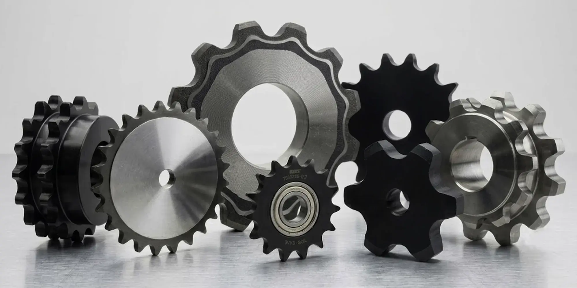
In roller chain drive systems, the number of teeth on the sprocket is important. It affects how well the system works. No matter what type of machine...
Quick AnswerA sprocket is a toothed wheel that meshes with a roller chain to transmit power — with zero slip. Unlike gears (which mesh with other...