Understanding Radial Load: A Key Factor in Motor Bearing Sizing
Motor bearing sizing is paramount to the functionality and longevity of a motor. Choosing the right bearing ensures efficient motor operation, while the wrong choice can lead to performance issues, premature wear, and even motor failure. Before selecting the appropriate size for motor bearings, it's essential to ascertain the motor load and associated bearing loads. Subsequently, determine the expected lifespan based on speed and load to choose the right bearing. Notably, gauging the radial load on the bearing is a pivotal step in this process.
This blog aims to demystify the concept of radial load, how to calculate it, highlighting its importance and its impact on motor bearing sizing, providing valuable perspectives for engineers, designers, and other industry professionals in pursuit of optimal system functionality.
What Is Radial Load?
Radial load refers to the perpendicular force exerted on the shaft of a motor. This force is predominantly influenced by various components such as gears, belts, and pulleys interacting with the motor shaft. These components, along with external forces they might encounter, contribute significantly to the overall radial load on the motor.
Radial Load Distribution of Motor Bearings
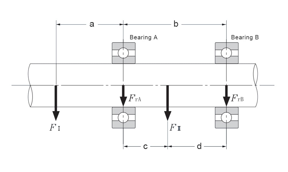
Think of the shaft system as a statically defined beam bolstered by bearings. The load on this shaft system gets evenly dispersed among its supporting bearings, as seen with bearings A and B in the illustration.
FrA=(a+b)FI /b+ dFII/(c+d)
FrB=-aFI/b+cFII/(c+d)
Where:
FrA: Radial load acting on bearing A N{kgf}
FrB: Radial load acting on bearing B N{kgf}
FI,FII: Radial load acting on the shaft system
This example is straightforward; however, most situations demand more intricate calculations.

Figure 1 Loads on bearing A and bearing B in the shafting system
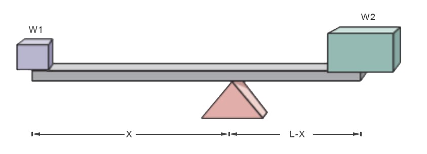
The "Lever Balance" Effect for Radial Load
The radial load varies based on the "distance from the gearhead output shaft's end." This distance signifies the gap between the shaft's end and the location where force is exerted on the shaft (the load's installation point). As the distance from the shaft's end grows, the permissible radial load also rises. This is because the load moves nearer to the internal support bearing within the gearhead flange. When the load is positioned closer to the support bearing, which acts as the fulcrum, it can bear more weight.

Calculation of Static Radial Loads
Static radial loads primarily arise from constant, unchanging forces that act perpendicular to the motor shaft.
Motor Weight
The rotor's weight exerts a static load. Use the weight of the rotor (often provided by the manufacturer or can be measured) and consider its distribution along the shaft.
External Forces
If there's any external equipment mounted on the shaft (e.g., pulleys, gears), calculate their weight and how it's distributed along the shaft.
Assembly Preloads
If the bearings are preloaded during assembly to remove any free play, this preload is a static force. Preload values should be provided in assembly documentation or can be measured using specialized equipment.
Total Static Load=Rotor Weight Load+External Forces Load+Assembly Preload
Calculation of Dynamic Radial Loads
Dynamic radial loads change over time and are influenced by operational conditions.
Rotor Imbalance:
Measure the imbalance using vibration analysis tools. This imbalance can be translated to force using the formula:
F=mω2e
Where:
F is the force due to imbalance
m is the mass of the rotor,
ω is the angular speed in rad/sec,
e is the distance of the center of mass from the axis of rotation (eccentricity).
Varying External Loads
If the motor is driving equipment where the load varies (like reciprocating pumps), you'd use performance curves or direct measurements to determine the dynamic component of the load.
Shaft Misalignment
Misalignment can be measured using alignment tools. Translating misalignment to dynamic radial force often requires specialized tools or software, as it involves complex calculations based on alignment data, motor and equipment specifications.
Thermal Expansion
Determine the change in length of the rotor/shaft due to temperature changes using the formula:
ΔL=L×α×ΔT
Where:
ΔL is the change in length,
L is the original length,
α is the linear expansion coefficient
ΔT is the change in temperature.
To convert this length change to force, you might need to use stiffness values and further calculations.
Vibration and Resonance
Use vibration analysis tools to measure the dynamic forces due to inherent vibrations or resonances.
Total Dynamic Radial Load
Sum up all individual dynamic loads. Note that some might be oscillatory, so you'd be looking for peak values or RMS (Root Mean Square) values for combined loads.
Total Dynamic Load = Imbalance Force + External Load Variation + Misalignment Force + Thermal Expansion Force + Vibration Force
How to do Motor Bearing Sizing after Locating Radial Load?
After determining the radial load, match the life expectancy of the customer according to the speed and load and select the bearing type.
Assess Operational Speed
Identify the range of operational speeds the motor will work within. Some bearings are better suited for high-speed operations, while others are designed for slower, high-torque scenarios.
Match Load to Bearing Ratings
Every bearing type has specific dynamic (for moving loads) and static (for stationary loads) capacity ratings. Ensure the chosen bearing can handle the calculated loads without risk of premature wear or failure.
Consider Bearing Life Expectancy
The expected life of a bearing, often given in terms of "L10 life," describes how long a bearing is expected to last before showing signs of fatigue. Use formulas like the one below to match your motor's expected operational life to a bearing with a suitable L10 life:
For ball bearings,
L10=(C/P)3
For roller bearings,
L10=(C/P)10/3
Where:
L10 is the bearing life in millions of revolutions;
C is the dynamic load rating of the bearing;
P is the equivalent dynamic load on the bearing.
Factor in Environmental Conditions
Bearings may need to be sealed or shielded if exposed to contaminants. Likewise, the choice of bearing lubricants can impact bearing longevity and should match the operational temperature and environment.
Conclusion
Understanding radial load is paramount in motor bearing sizing, ensuring efficiency and longevity. Accurate calculations are crucial, guiding proper motor selection tailored to specific operational requirements. For those seeking expertise in this arena, LILY Bearing stands as a trusted resource, offering a comprehensive range of bearing solutions to meet diverse industrial needs.
Keep Learning


